Meet the Presenter
This article is based on a webinar titled Lubrication of Innovative Engineered Bearings and Industrial Motion Components. Hosted by the American Society of Mechanical Engineers’ (ASME) Tribology Division and presented by STLE Past President Dr. Ryan Evans on Nov. 15, 2023, the session explored rolling element bearings, battery electric vehicle wheel bearing considerations, lubrication systems, gear drives and more. Courtesy of STLE, this article captures the core insights from this ASME-organized event. For more technical content from the ASME Tribology Division Webinar Series, visit the ASME Tribology Division’s website here.
Dr. Ryan Evans is the director of R&D at The Timken Co. where he is a global lead for R&D activities, including the identification and development of new products, materials and manufacturing technologies. He joined Timken more than 20 years ago. As a researcher in the field of advanced materials, he has made significant contributions in areas of thin film coatings, lubrication, advanced materials, characterization and tribology. He has more than 60 technical publications and 14 patents in this field. Evans has a doctorate degree in chemical engineering from Case Western Reserve University in Cleveland, Ohio, and is a Fellow of ASM International and STLE. He recently completed a term as STLE president in 2022-2023.
You can reach him at ryan.evans@timken.com.

Dr. Ryan Evans
KEY CONCEPTS
•
Lubricants are the lifeblood of rolling element bearings and industrial motion component products. Improper lubrication accounts for >50% of all bearing failures, followed by equipment misalignment and installation issues.
•
There are four general classes of rolling bearings: ball bearings, spherical roller bearings, cylindrical roller bearings and tapered ball bearings.
•
Battery electric vehicles (BEVs) use new bearing designs as BEVs are heavier than internal combustion engine vehicles (ICEs) and have a lower center of mass with higher power. This means BEVs may need a higher rated bearing for both load and speed.
•
Advanced manufacturing systems include robotic components that have complex lubrication requirements. Automated lubrication systems are beginning to address these needs.
Tribological hardware manufacturers rely on lubricants as the lifeblood for their rolling element bearings and industrial motion component products. This article introduces engineering rolling element bearings, then discusses modern applications and lubrication-related technologies as they help to drive high level progress on topics like sustainability, energy efficiency and battery electric vehicles (BEVs).
This article is based on a webinar presented by STLE Past President Dr. Ryan Evans, director of R&D at The Timken Co., and the Tribology Division of the American Society of Mechanical Engineers (ASME) titled Lubrication of Innovative Engineered Bearings and Industrial Motion Components. See Meet the Presenter for more information.
Few people realize how much tribology is involved in industrial motion components outside of classic rolling element bearings. Several drive devices that involve strain wave and cycloidal reduction can be found in robotic joints, as well as automated lubrication systems and linear motion bearings and how they can help automate the factories of the future. Along with the critical role of lubrication, this article includes future opportunities for innovation.
Rolling bearings
There are four general classes of rolling bearings
(see Figure 1):
•
Ball bearings are the most common. Balls are spaced around the circumference of an inner ring and an outer ring. Usually the inner ring is mounted to some type of shaft that is rotating while the outer ring is fixed; however, in some instances this configuration is reversed.
•
Spherical roller bearings (SRBs) are not ball bearings, even though balls are spheres. The rolling elements themselves are barrel shaped, and the outer ring raceway has a single-radius profile that accommodates two rows of rollers and allows operation with some misalignment.
•
Cylindrical roller bearings (CRBs) are like SRBs with inner and outer rings, but with cylindrically shaped rollers and raceways that are parallel to the bore and outer diameter surface of the inner and outer rings.
•
Tapered roller bearings (TRBs) are like CRBs but with truncated conical rollers and slanted raceways to accommodate them.
Choosing which bearing to use in a particular application depends on the loading profile, which is illustrated by the size and direction of the arrows in Figure 2. The vertical arrows illustrate radial loading, while the horizontal arrows illustrate axial loading. From left to right, the figure shows ball bearings, CRBs, SRBs and TRBs. As shown by the arrows, the roller bearings can accommodate higher radial loads than ball bearings. Rolling element geometry most directly influences the bearings’ ability to accommodate axial (thrust) loading.
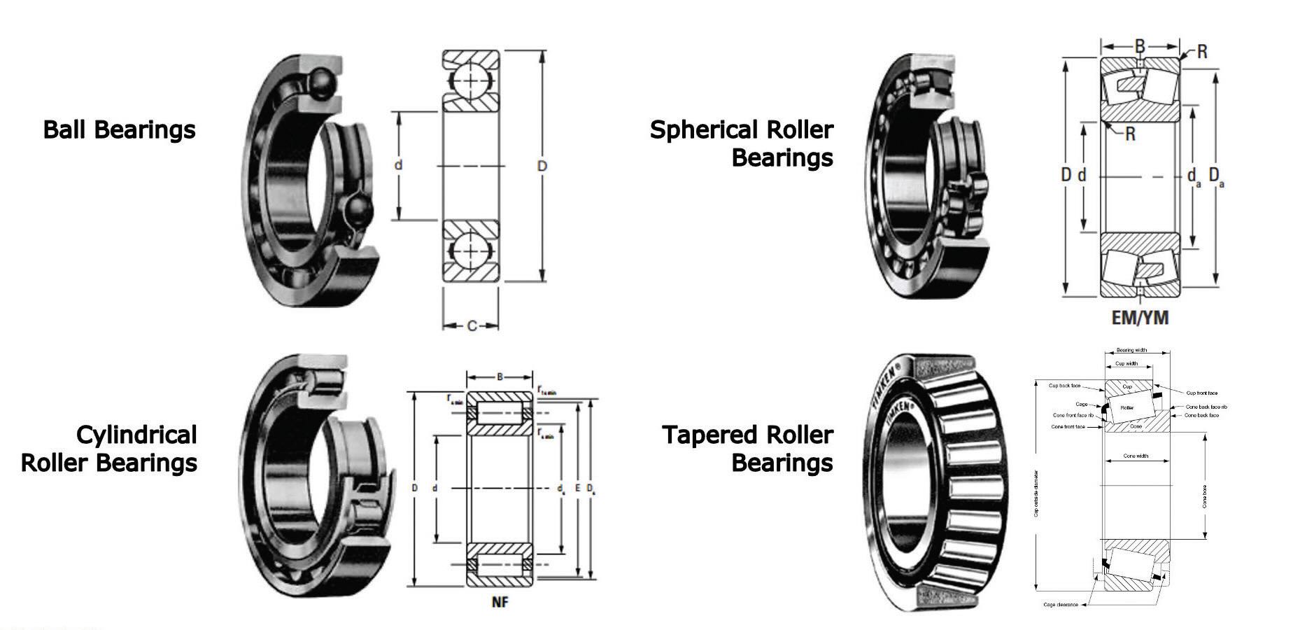
Figure 1. Four general classes of rolling element bearings.
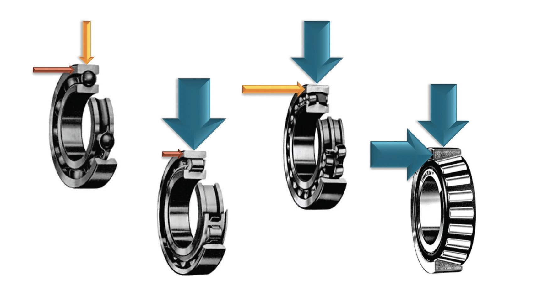
Figure 2. Choosing which bearing to use in a particular application depends in part on the loading profile.
The reason for the different loading considerations between bearing types is the microscopic contact geometry. Ball bearings have single points of contact where the ball touches the raceway. TRBs, SRBs and CRBs have a line contact geometry, meaning the contact between the rolling element and the ring raceway is maintained across a wider length, allowing more contact area to distribute the higher loads and thereby reduce local contact pressure.
With TRBs, the outer rings are called “cups” and the inner rings are called “cones” because the outer ring has a cup shape. The rolling element spacer is called a “cage” or “retainer.” TRBs allow for adjustable axial settings, which can be an advantage in that they can be mounted to set internal clearances and load zones to suit application friction management and load bearing needs.
Battery electric vehicles (BEVs)
BEVs are an application area benefiting from new bearing designs. BEVs tend to be heavier than a similarly sized internal combustion engine (ICE) vehicle and have a higher gross axle weight rating (GAWR). While the need for a gas engine and transmission are eliminated, the batteries, and electric motor(s) and associated gearboxes, can be heavier than the ICE. The vehicle center of gravity also is lower in a BEV because the batteries are mounted lower to the ground, typically near axle height.
BEV motor gearboxes are often intended to connect directly to drive shafts and axles the same as ICE powertrains. Wheel end development is thereby minimized by using existing components (i.e., knuckles, constant velocity [CV] shafts, hub/bearing). Wheel bearing design requires bearing life analysis to estimate how many miles the wheel end can survive before requiring replacement. With BEVs the bearing load capacity of the wheels must be increased to account for the heavier weight vehicle. Bearing assembly stiffness is engineered to minimize the risk of bearing misalignment and hub fatigue, and reducing frictional power loss also is a goal. Standardizing common parts and minimizing the need for new components also is a benefit when designing wheel end bearings for BEVs.
Wheel end bearings for BEVs are most often sealed and grease lubricated. As battery weight adds to GAWR, greases with higher load-carrying capacity may be needed, requiring higher viscosities and non-standard extreme pressure (EP)/antiwear (AW) additives. Antioxidants also may be needed due to higher temperatures that result from higher loads and viscosity requirements. Torque calculations are used to achieve proper balance among these factors so that the power loss performance of the grease within the wheel is understood.
BEVs require an upsized ball bearing with a larger ball diameter in the wheel compared to ball bearings for ICEs to account for a BEV’s lower center of mass and higher GAWR. In other words, BEVs require a ball bearing with a higher load capacity than an ICE ball bearing version of the same vehicle. However, an alternative to simply using larger wheel end ball bearings in a BEV is to change to a TRB wheel end bearing. Changing from a point contact ball bearing to a line contact TRB allows the bearing unit to be smaller in size while accommodating the same loading levels. Compared to a ball bearing wheel end hub unit, TRB designs have a smaller roller diameter (as compared to ball diameter) with more rolling elements per bearing row. The dynamic capacity for the same basic wheel end packaged bearing unit size actually goes up for the TRB compared to a similarly rated ball bearing unit.
Electric axle key application drivers
Another application space for rolling element bearings in BEVs is electric axles
(see Table 1). A conventional light truck rear axle center has hypoid gears with the shafts running at approximately 5,000 rpm with an operating temperature of approximately 85℃ in a cast iron housing. In contrast, some BEV designs operate with a two- or three-shaft gearbox driving an output shaft with the differential. Operating speeds are much higher, in the range of 10,000-20,000 rpm, and often helical gears are selected to minimize friction in the parallel shaft gear set. BEV axle gearboxes typically operate at higher temperatures with lightweight aluminum housings. Further, the desire to minimize friction losses and improve heat transfer in these gearboxes make lubrication design quite challenging, sometimes requiring ultra-low viscosity lubricants. Some of these emerging lubricants are called electric driveline fluids (EDFs) and are designed for lubricating high-speed helical gears and bearings, but also for heat removal for thermal performance.
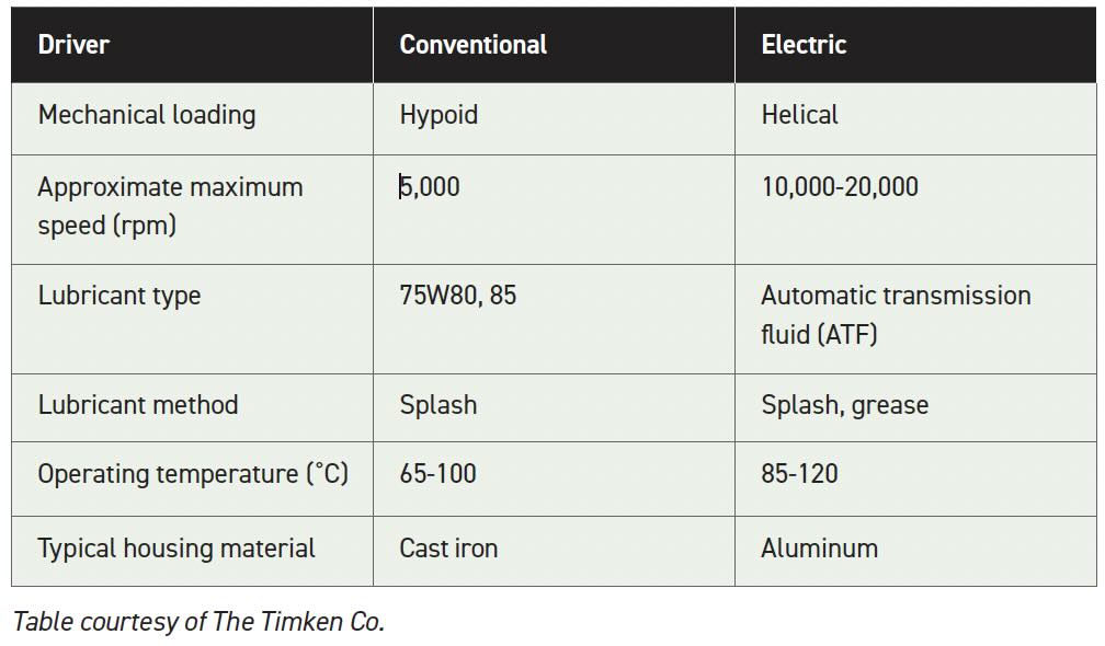 Table 1. Electric axle key application drivers
Figure 3 shows example electric axle bearing configurations. Usually for higher speeds at the input shaft, ball bearings are appropriate as the point contacts allow lower friction at high speeds. However, at the intermediate and output shafts, the shaft speed is reduced, and specially engineered line contact bearings like TRBs may be preferred for load management and a small profile within a tight gearbox architecture (i.e., power density).
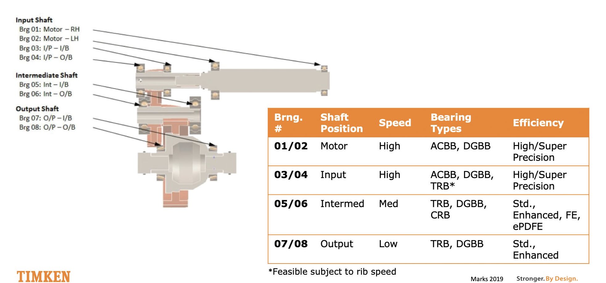 Figure 3. Example schematic electric axle bearing configurations.
A risk in these BEV gearboxes is the tribological challenges present with lower viscosity oils used for higher efficiencies operating at high speeds. If bearing cage damage occurs, thermal runaway or scoring wear can occur. In addition, a lubricant film must be maintained in the rolling/sliding contact between the roller ends and the ribs or inner ring flanges in TRBs, especially at high speeds, and the use of low-viscosity oils can create wear challenges with improper designs. These are just a few of the tribological considerations that have to be solved in selecting lubricants, bearings and gear combinations for these axles.
Deep groove ball bearings (DGBBs) or TRBs (i.e., electric application power-dense fuel-efficient [ePDFE] TRB) can be used to downsize BEV gearbox bearings on intermediate and output shafts to take advantage of the high load-carrying capacity of line contacts versus point contacts
(see Figure 4). However, these tend to be more custom designs at this time. TRBs offer small size, weight and load-carrying benefits and higher inherent stiffness. Simulated power losses for DGBBs and TRBs show no significant differences under common duty cycles. Questions remain about the long-term wear resistance of TRBs under high-speed and low-viscosity lubrication conditions, but early modeling and experimental data are encouraging.
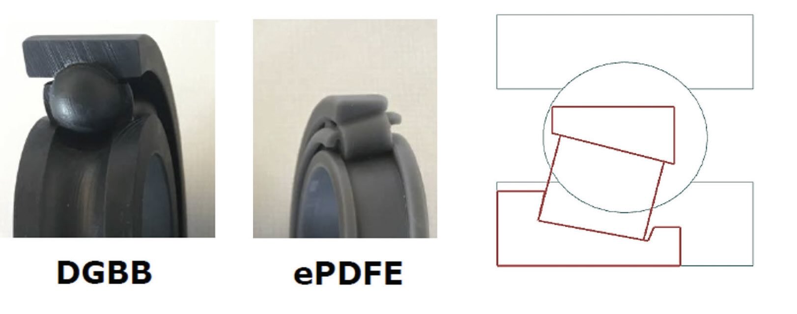 Figure 4. Polymer 3D printed models to scale of DGBBs and an ePDFE TRB designed for electric axle applications.
Bearing lubrication
With line contacts like those in tapered, cylindrical or SRBs, understanding lubricant properties is critical because the lubricant separates the rolling element from the raceway surfaces. Frictional power losses within bearings occur from several different mechanisms related to local lubrication conditions, elastic hysteresis and bulk lubricant churning and drag. In particular, full film, mixed film and boundary film localized lubrication conditions between contacting surfaces within the bearing assembly each have different frictional characteristics. All of these losses need to be understood to calculate the total power loss within a rolling element bearing.
Understanding how viscosity changes within the lubricant under very high pressure is a goal as engineers seek to understand overall bearing operating efficiency. Lubricant shear losses are significant and dependent on the lubricant thickness. The loss mechanism is dependent on Λ (lambda), a dimensionless film thickness parameter. Boundary friction occurs when there is no film separation, meaning the friction is governed by the surface chemistry of the solids. With mixed friction, there is some asperity contact combined with some hydrodynamic separation. In full film thickness there is complete separation between surfaces through hydrodynamic separation, and hydrodynamic friction depends very directly on the lubricant rheology.
As low viscosity lubrication trends continue, an accurate understanding of rheological properties becomes more critical for efficient bearing design. Experimental high-pressure rheological measurement instruments and analytical tools are employed to predict sliding friction in rolling element bearings
(see Table 2). Measured rheological data fit with modern models show a reduction in mean error for power loss predictions compared with experiments. Modern models also can be utilized in other larger-scale bearing or system calculations.
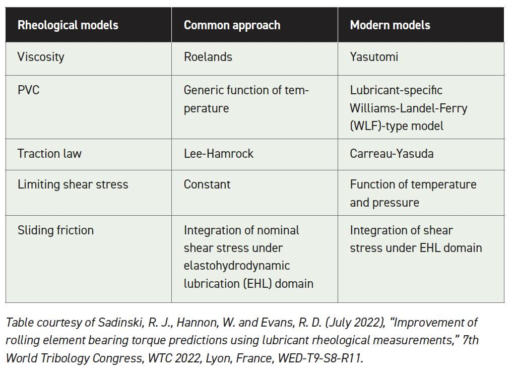 Table 2. Approaches to rheological models
Tribological coatings in bearings
Tribological thin films on the surfaces of bearings are unavoidable. If the system runs with base oils only, natural oxide layers form on the bearing and contacting surfaces—especially under boundary or mixed film lubrication conditions. Lubricant formulators may add additives to oils that are designed to improve friction or wear performance by reacting with the bearing surfaces to form tribological films often containing iron and oxygen, but also sulfur, phosphorus, calcium, zinc and other chemical elements. Engineers can design bearing surfaces using black oxide treatment and other approaches to accomplish some operating advantage. A more advanced approach is to deposit thin films that intentionally have beneficial material properties to improve surface durability.
Tribological contacts in boundary lubrication are susceptible to adhesive, abrasive and other types of wear. Several types of tribological thin films can combat this wear. The contact mode matters (i.e., rolling versus sliding). Black oxide and other diamond-like carbon (DLC) coatings are common in wind applications of rolling element bearings.
One example of those coatings is amorphous hydrogenated carbon containing tungsten (a-C:H:W), which is a nanostructured composite coating, usually only one- to two-microns thick as shown on the high resolution transmission electron microscopy (HRTEM) photo in Figure 5. The dot clusters on the image are the crystalline carbides within the amorphous hydrocarbon matrix. This material can be used to coat rolling elements to reduce wear under poor lubrication conditions. The benefits include reduced wear through improved micropitting resistance and improved smearing/scuffing resistance. This coating also improves rolling contact fatigue life through low Λ or poor lubrication conditions or in debris-contaminated environments.
1
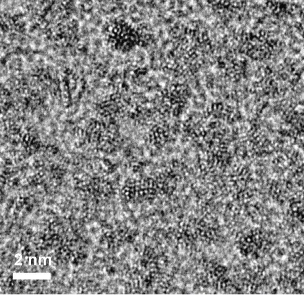 Figure 5. High resolution transmission electron microscope image of an example a-C:H:W (i.e., diamond-like carbon or DLC) coating sometimes applied to rollers in bearings to improve wear resistance.
The role of these coatings and the tribology of bearings under electric current exposure also is being studied. Recent laboratory studies are confirming that even low levels of electric current passage in rolling element bearings can accelerate damage such as white-etch cracking, micropitting and other surface damage.
2 Stray current risk is yet another consideration for design engineers in applying rolling element bearings as electrification trends progress.
It was shown that special rolling element bearing designs optimize application reliability in BEV applications. The lower center of gravity in BEVs may require adjustments to wheel end bearing designs. TRBs (ePDFE) can meet the tribological demands of e-axles and compete with DGBBs for specification into these applications for power-dense designs. Modern rheological test equipment and updated models dramatically improve the bearing power loss (i.e., efficiency) calculation accuracy for difficult applications. Opportunities for tribological coatings in bearings exist in the fields of transportation, energy, manufacturing and environmental sustainability.
Industrial motion components
Advanced manufacturing system trends include robotic material handling, “lights-out” or “dim-lights” manufacturing and lean flow processes. These types of manufacturing configurations emphasize improved material utilization and waste reduction, automated process control and feedback dashboarding and on-machine and non-contact gauging and inspection, operated by only a few skilled people. This is enabled through advanced manufacturing automation with smarter equipment and advanced friction management technologies. As modern factories rely more and more on robotics and automated equipment operations, the sheer number of tribological components like bearings, gears and other power transmission components become challenging from a maintenance point of view.
One focus area is the use of automated lubrication systems to administer the right amount of grease at the right time to factory equipment assets. Improper lubrication accounts for >50% of all bearing failures, followed by misalignment and improper installation issues.
3 With automated lubrication systems, plant engineers can feel confident that their equipment lubrication maintenance is under control without needing a maintenance person to manually regrease critical lubrication points. A pump automatically applies lubrication to equipment and bearings during operation, with no equipment downtime, to eliminate labor tasks and improve reliability. Automatic systems also apply lubrication to equipment at much shorter time intervals than manual application. This has the potential benefits of keeping equipment lubrication at optimal levels while enabling higher equipment productivity and improved safety. These systems are configurable to application needs, including manufacturing applications in metal, mining and recycling, for example.
Strain wave gear drives are a type of mechanical drive that can enable high gear reduction ratios in a compact package. Strain wave gear drives can be designed as torque-dense gear drive modules, with high positional accuracy, high torsional stiffness and zero backlash
(see Figure 6). High ratio reduction in a single stage makes these gear drives perfect for light-duty robotic and positioning joins. There are a variety of sizes, output torques and output ratios available (e.g., 160:1). Strain wave gear drives are assembled and lubricated in a class 8 clean room environment. The drive components are machined into matched sets that do not permit the mixing of components. Most drives are grease-lubricated with a required change after the first 100 hours and then again every 2,000 hours or 12 months of use. Care should be taken when disassembling these units, and all manufacturer lubrication instructions should be followed, including the recommended break-in procedures after maintenance.
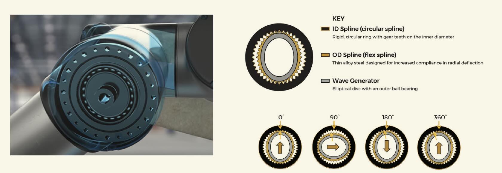 Figure 6. Strain wave gear drives.
Cycloidal reduction gearing is created when eccentricity on a rotating shaft generates cycloidal movement that carries the needles in the case with rolling motion. These drives are used in similar application spaces as strain wave gear drives, but typically can accommodate higher torque capacity by comparison in a larger package. These gears have a high number of moving parts, but offer high precision, zero backlash and a compact design with high torsional and tilting stiffness. Cycloidal reduction gear drives are lubricated with either grease or oil to the manufacturer’s recommendations
(see Figure 7). These lubricants cannot be mixed with other lubricant types and the manufacturer guidelines specify the amount of grease or oil needed per specific drive unit (e.g., approximately 80% of free volume). The lubricants need to be drained and refilled to keep the equipment in the best condition. Taking these drives apart and putting them back together after regreasing requires precision and diligence, given that some have as many as 300 pieces.
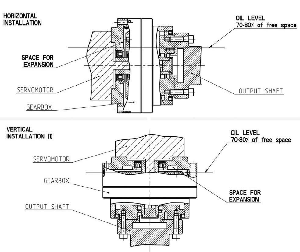 Figure 7. Cycloidal reduction gear drives.
A wide variety of linear motion bearings can be used to enable warehouse automation, including vertical storage, stacker cranes, vertical conveyors and shuttle rails for storage. Every one of these moving parts and bearings needs lubrication, but their needs can be very different ranging from a full synthetic oil to lithium grease. They can require frequent lubrication and maintenance, making automated lubrication systems especially helpful.
Conclusions
Diverse requirements for lubrication of engineered bearings and industrial motion components were discussed in this article. Of particular interest are BEV applications, where bearing selection affects BEV performance and size as engineers work to reduce vehicle weight and frictional power losses. Wheel end and e-axle bearings for BEVs may be subject to different operating conditions than their equivalents in ICE vehicles, including higher loads, higher speeds and with a desire to use thinner or lower viscosity lubricants. There is movement toward improving the precision of energy efficiency or friction calculations for rolling element bearings in general, making the need for accurate rheological data for lubricants more important. Advances on this front will improve the bearings needed for critical transportation, energy, manufacturing, environmental sustainability and renewable energy type applications.
In addition to BEVs, advanced manufacturing systems are another exciting area for bearing and component lubrication advancements. Many of these modern systems use compact drive units in robotics that often require complex lubrication protocols given their mechanical complexity. This equipment has unique lubrication needs that automated lubrication systems are beginning to address effectively as well.
REFERENCES
1.
Doll, G.L and Evans, R. D. (Oct. 17-21, 2010), “Solving wind turbine tribological issues with materials science,” Materials Science & Technology (MS&T) Conference Proceedings (Houston, Texas) pp. 2158-2169.
2.
Sanchez, L. J., Hager Jr., C. H. and Evans, R. D. (2024), “Rolling element bearing damage in the presence of applied electric current,”
Tribology Transactions, 67 (3), pp. 602-613.
3.
Hannon, W. M. and Ai, X. (2013), “Rolling bearing lubricants,” in
Encyclopedia of Tribology, Springer, Boston, Mass., ISBN: 978-0-387-92896-8.
Andrea R. Aikin is a freelance science writer and editor based in the Denver area. You can contact her at pivoaiki@sprynet.com.