Couplings and their lubrication
By Dan Holdmeyer, Contributing Editor | TLT Lubrication Fundamentals September 2024
Proper coupling lubrication not only requires selecting the proper lubricant for the size, speed and type of coupling but filling the coupling to the right level.
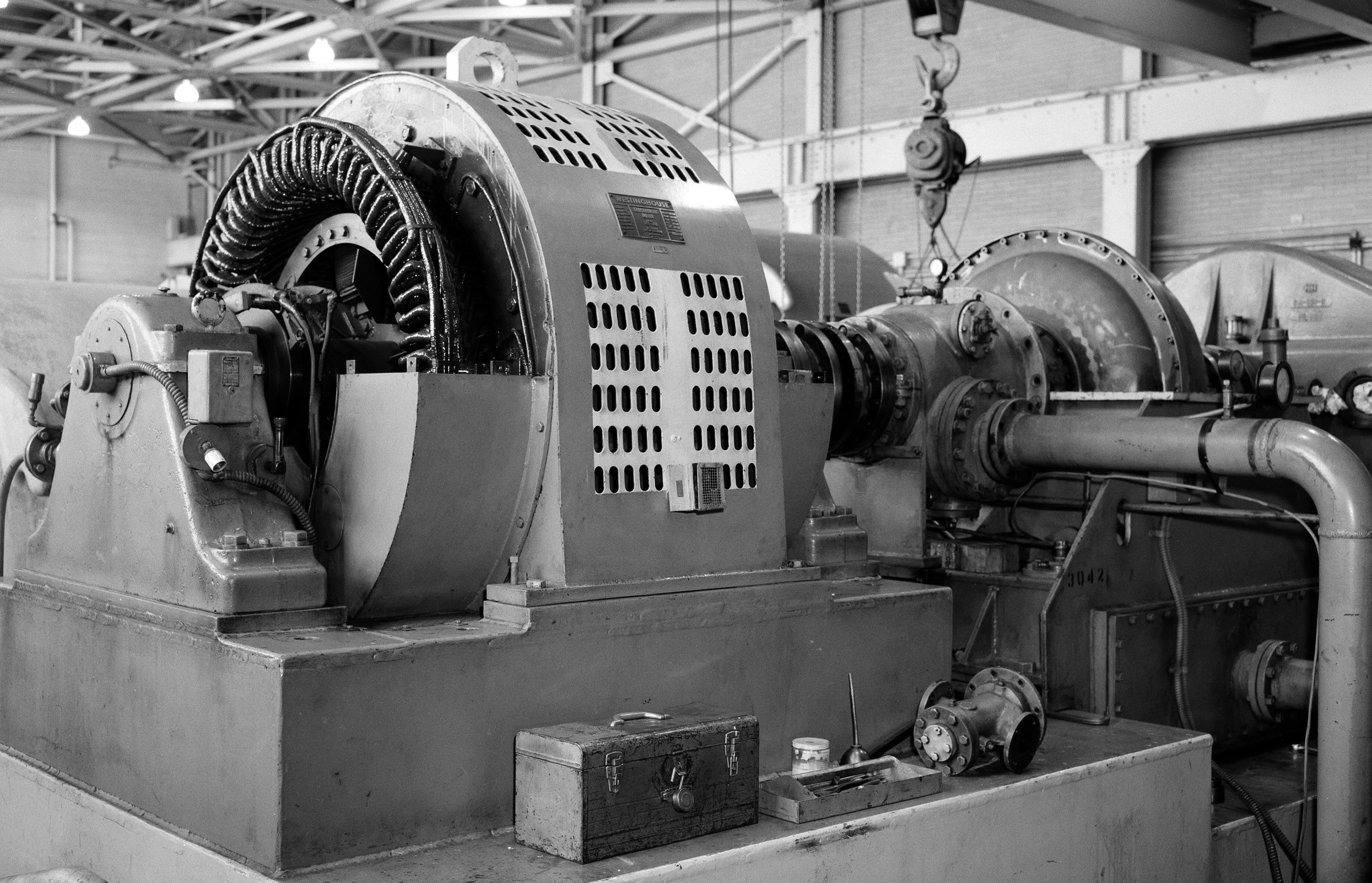
Photo courtesy of Defense Visual Information Distribution Service.
Shaft couplings, commonly just called couplings, link two shaft ends together to transmit power from one shaft to another. Rigid couplings, such as shown in Figure 1, transmit power from a driving shaft to a driven shaft usually within a rigid framework where the shafts maintain alignment.
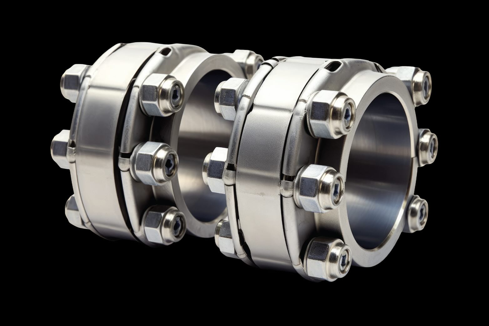
Figure 1. Precision rigid coupling.
Flexible shaft couplings (see Figure 2) transmit power from one shaft to another but are designed to also accept shaft misalignment. Typically these are required for connecting shafts between two machines or components not held in place within the same solid frame. Examples of this are a motor driving a gearbox driving a pump, an engine driving a compressor or a turbine driving a generator.
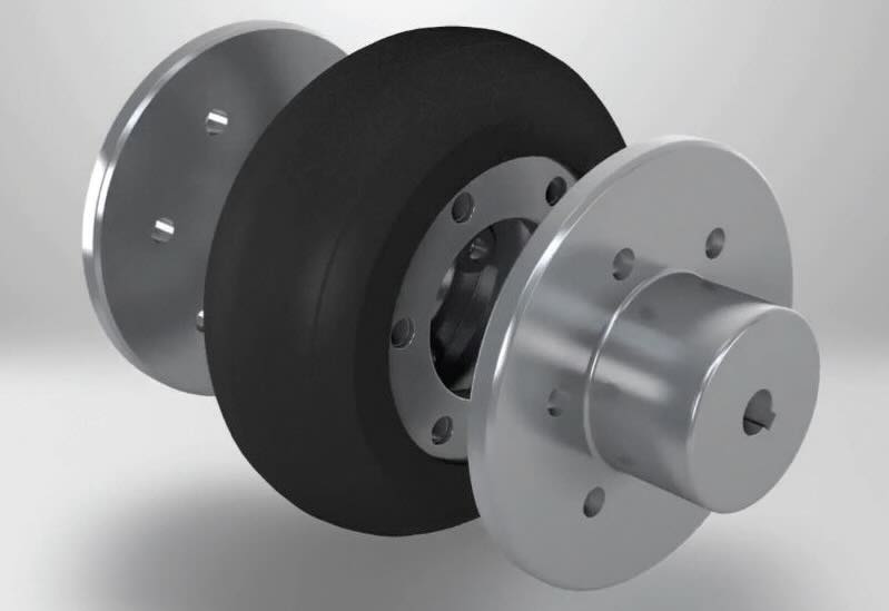
Figure 2. Flexible polymer coupling. Figure courtesy of Richard Kim, CC BY-SA 4.0, via Wikimedia Commons.
Setting machines so the adjoining shafts are precisely aligned is difficult. It takes considerable skill, knowledge and time. Perfect alignment of joining shafts between machines is a rarity, but slight misalignment may be beneficial for some flexible couplings, as we’ll discuss when we talk about lubrication of certain couplings.
Even perfectly aligned shafts are subject to misalignment as they are run due to varying thermal expansion of the aligned components or machines. Additionally, alignment may be knocked out of alignment by vibrations, being bumped or even by the work the machinery is performing.
Three shaft misalignments are eccentric, angular and axial. Eccentric, or radial, misalignment occurs when the shaft centerlines are offset from each other. One component being higher or lower than or to the right or left of the other would lead to radial misalignment. Generally, the shafts are parallel to each other, but their centerlines are offset. Angular misalignment is when the shafts are not parallel to each other. As the name implies, the shafts intersect at an angle. Eccentric and angular misalignment may occur horizontally, vertically or at some degree of each. Axial misalignment is when the shafts are separated from each other axially. This is generally needed to accommodate thermal expansion of the shafts. Too much or too little separation results in excess stress on the bearings, and other components of each of the coupled components, just as eccentric and angular misalignment does.
Shaft couplings transmit power and can accept certain degrees of misalignment, but they also can help protect components from other equipment maladies. Couplings help dampen vibration transmission from one component to another and reduce the shock of torque changes. Certain couplings also can provide electrical isolation of each component as well as inhibit heat transfer from shaft to shaft.
With all the aforementioned issues with coupling shafts together, a myriad of coupling designs, made with different materials, are available to accommodate specific needs. Transmitted torque, speed and allowable degree of misalignment are included in specifications design engineers need to consider when choosing the coupling design. Figure 2 shows a coupling made with a polymer. Others may be made with a steel-flex plate.
A coupling not typically called a coupling, that many people not as familiar with industrial machinery couplings may sooner recognize, is the combination of the drive shaft and universal joints in rear-wheel-drive vehicles. The drive shaft transfers power from the transmission to the differential and drive axles. The transmission output shaft is typically on a horizontal plane above the plane of the differential input shaft resulting in eccentric or radial misalignment between the two shafts. The drive shaft is connected via universal joints at an angle to each of these shafts, thus compensating for the radial misalignment. The universal joints can then handle the angular misalignments of the drive shaft with the transmission output shaft and differential input shaft. Figure 3 shows the spider, or journal cross, with a grease zerk for lubricating the needle bearings on each of the four cross shafts. Yokes attached to the drive shaft and the transmission output shaft, or the differential input shaft, are attached to the needle bearings of the journal cross.
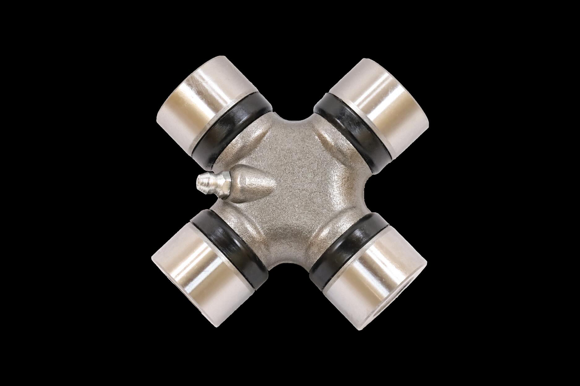
Figure 3. Universal joint.
The drive shaft must compensate for the axial misalignment, or the distance between the transmission and the differential. This axial misalignment is not static and is much more dynamic than the thermal expansion we discussed earlier. The axial misalignment visibly changes when the vehicle is loaded with cargo or when the vehicle bounces over rough terrain or road potholes. The differential and drive axles are connected to the vehicle frame via shocks and springs, allowing the differential and axles to move up and down relative to the frame of the vehicle, resulting in the differential moving closer and farther away from the transmission, which is held more rigidly to the vehicle frame. Thus, the drive shaft consists of two shafts connected via splines to transmit power that also slide in and out, making the drive shorter and longer, respectively. Figure 4 shows spline shafts with external splines that would be connected to another shaft with internal splines.
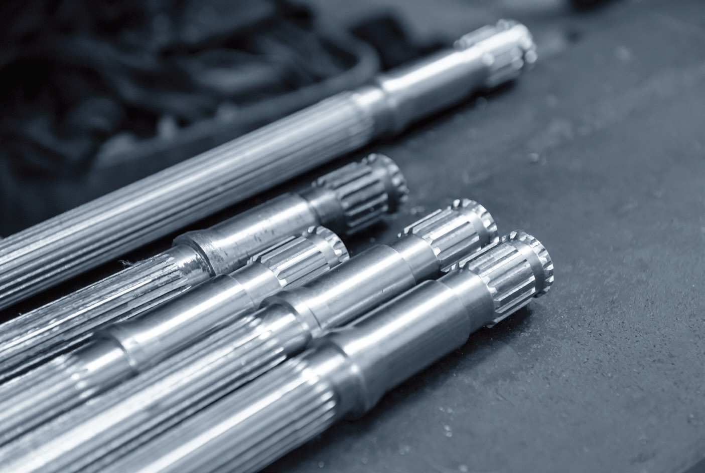
Figure 4. Shafts with external splines.
The universal joints and the spline shafts each are couplings; however, it is the combination of the two that compensates for the three forms of misalignment between the transmission and the differential. These couplings are typically lubricated with a good quality #2 grade, National Lubrication Grease Institute (NLGI) GC-LB certified grease. Some vehicle drive shafts and universal joints are lubricated for life. Universal joints and sliding spline shafts may be found in industrial applications as well.
Front-wheel-drive and all-wheel-drive vehicles use constant-velocity joints (CV joints) (see Figure 5) instead of universal joints. CV joints transmit power through a wider range of angles without loss of speed or significant increase in friction. CV joints are lubricated for life with a molybdenum disulfide grease. The grease is held in the joint by a rubber boot, which also keeps out contaminants. The CV joint is stronger than the universal joint; however, if the protective rubber boot is torn, the joint will quickly fail.
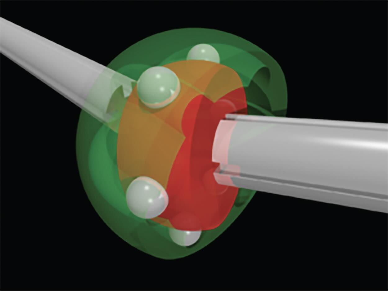
Figure 5. Constant velocity joint.
Many of the flexible couplings in industrial applications deal with greater torque, which requires larger shafts, but much less misalignment, versus automotive applications. Earlier, we mentioned a couple of the myriads of different flexible couplings made with polymer or flexible steel components. These do not require lubrication as they don’t have any sliding parts.
There are three industrial-type flexible couplings that require lubrication: gear, grid and chain couplings. Gear couplings (see Figure 6) provide the greatest torque transfer capacity of any flexible coupling of equal size. The hubs have external gears that mesh with the internal gears of the flanges. The lubricant is contained in the coupling and the centrifugal force from the coupling rotation forces the lubricant out to the meshing teeth to minimize wear. This is where slight misalignment helps lubricate the coupling’s gear teeth. The movement of the gear teeth relative to each other creates a wedge that draws the lubricant between the teeth.
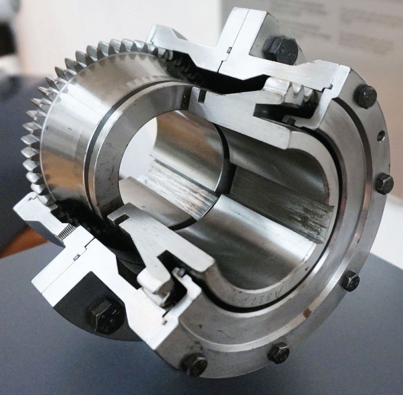
Figure 6. Gear coupling. Figure courtesy of Tiia Monto, CC BY-SA 3.0, via Wikimedia Commons.
Grid couplings utilize a pair of hubs with “channels,” or slots, through which a “grid,” or steel ribbon, is woven connecting the hubs and, thus, the shafts with which the hubs are attached to transmit power. The steel ribbon provides flexibility to absorb shock loading and accommodate a wider range of misalignment than the gear coupling. Lubrication is like that in the gear coupling, taking advantage of the centrifugal force generated by the coupling rotation and the relative sliding action between the ribbon and the slots, generated by slight misalignment, to maintain a lubricant film between the sliding surfaces.
Chain couplings mainly consist of a pair of sprocket hubs connected via a double- strand chain to transmit power from shaft to shaft. The clearances between the chain and sprockets, as well as clearances within the chain, absorb shaft misalignment. The chain coupling is limited to low or medium torque and speeds, but they are less expensive and more compact than gear couplings. Lubrication is again achieved like the gear coupling with the centrifugal force putting the lubricant where the sliding action between the components helps maintain the lubricant film. Some chain couplings use nylon chains to eliminate the need for lubrication in low torque applications.
Grease is generally preferred over oil lubrication of these industrial flexible couplings mainly due to less leakage from the coupling with grease. Whether oil or grease, the oil needs to be viscous. International Standards Organization (ISO) Viscosity Grades 680 to 1500 are common. The lubricant also needs anti-scuff, or extreme pressure, additives to minimize wear under heavy and shock loads.
Another critical specification for coupling grease is oil separation resistance. Coupling grease is subject to great centrifugal forces, which separates the oil from the grease thickener much faster than “oil bleed” found in grease containers stored for a long time. Therefore, the thickener density needs to be closer to the density of the oil than in other greases. Most non-coupling greases have thickeners denser than the oil, so the thickener would move to the outer circumference of the coupling, where the mating gear teeth or steel ribbon and slots need to be lubricated, but without the oil that does the actual lubricating. The oil will collect in the center of the coupling away from the load-carrying, wear-prone components of the coupling. A good quality coupling grease will have low oil separation, which is different than oil bleed performance. The American National Standards Institute/American Gear Manufacturers Association (ANSI/AGMA) have developed coupling grease standards that specifically address load carrying and oil separation requirements amongst other specifications. The standards are AGMA CG-1, CG-2 and CG-3 type. A good quality coupling grease will meet any or all these requirements, which correspond to the operating conditions for which they are designed.
Proper coupling lubrication not only requires selecting the proper lubricant for the size, speed and type of coupling but filling the coupling to the right level. Thermal expansion of an over-filled coupling will lead to lubricant leakage, coupling damage and plant safety issues. An underfilled coupling will lead to premature wear. Lubricated couplings should be checked regularly for signs of leakage and vibration. These couplings generally require relubrication every six months to a year. Ideally, the coupling is taken completely apart for thorough cleaning, inspection, relubrication and assembly. Relubrication between inspections is not uncommon, but caution must be taken to not over fill the coupling.
Fluid couplings are another category of couplings that are more designed to engage and disengage a driver, such as a turbine or engine, to a machine than to compensate for misalignment. A good example of this type of coupling is the torque converter in automotive transmissions as we discussed in the March 2024 TLT Lubrication Fundamentals article titled “Automotive transmissions.” Industrial fluid couplings usually require either an automatic transmission fluid (ATF) or a turbine oil of ISO VG 32-68. The industrial fluid coupling, such as shown in the title photo of this article, also may have an oil circulating system to help cool the oil.
Flexible couplings are relatively small components that play a critical role in protecting major pieces of equipment in industrial and automotive applications. Lubrication, in some, routine inspections and proper maintenance help maintain equipment reliability and prolong life.
Dan Holdmeyer is retired from Chevron Lubricants and is based in Washington, Mo. You can reach him at dan.holdmeyer@gmail.com.