The tribology of train wheels
By Dr. Edward Becker, Contributing Editor | TLT Automotive Tribology August 2024
There is a simple but elegant solution to the problem of slip in train car wheels.

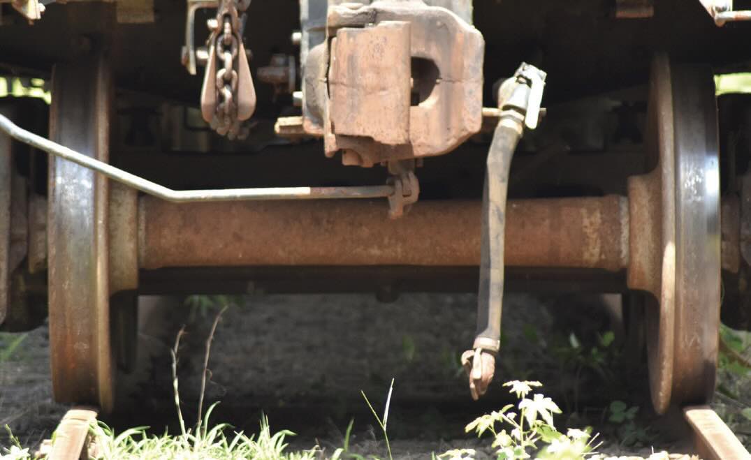
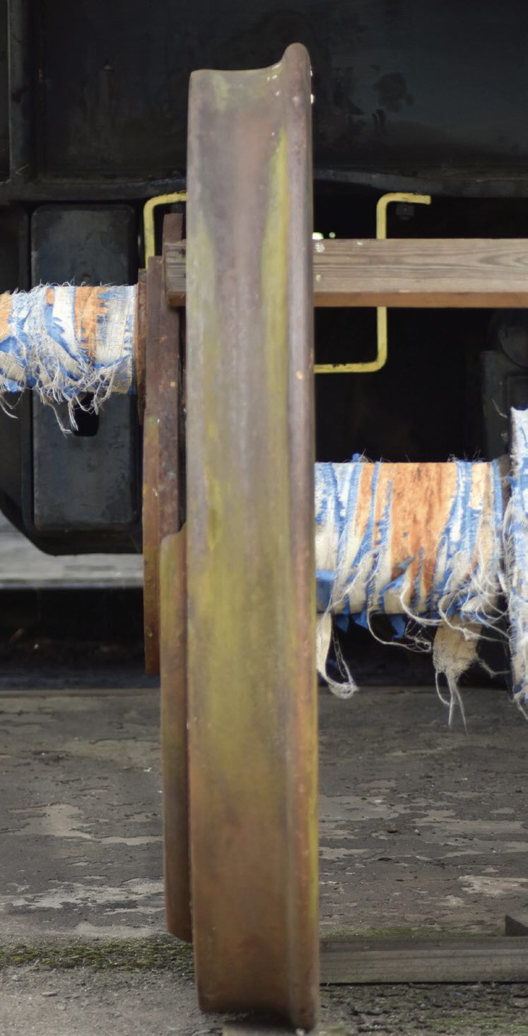
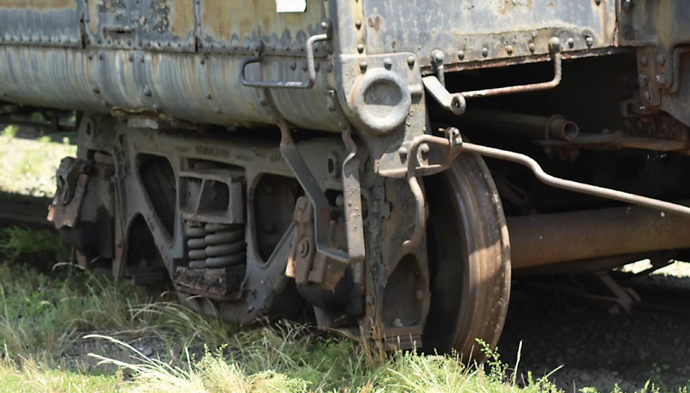
The wheel from an old express milk car. Photo courtesy of Southeastern Railway Museum.

A driving wheel from a steam locomotive that dates back to the 1880s. Photo courtesy of Southeastern Railway Museum.

The truck set from the milk car. Photo courtesy of Southeastern Railway Museum.
Long-distance motorized transportation became available, at least to the well-off adventure seeker, in the early to mid-1800s. Steam power was being implemented to ocean-going ships and to land-based locomotives. The trains pulled by locomotives were first widely used to move cargo but quickly came to accommodate passengers. The cars pulled by locomotives provide an interesting lesson in the tribology of wheels.
Train cars run on wheel sets. Each wheel set consists of two wheels mounted on a solid axle. Two or more wheel sets are used per rail car. This fixed arrangement means the wheels attached to an axle must rotate at the same angular speed. This situation is fine when the train is moving along a straight set of tracks, but what happens when the train rounds a curve?
The geometry of a curve dictates that the outer wheel must move over a greater distance than the inner wheel. If the wheels have the same diameter, then one or both of the wheels would slip (rather than purely roll) along the rails. Slip is a problem from a tribological standpoint; slipping causes energy loss due to sliding friction and also can result in wear of both the wheel and rail.
The solution is both simple and elegant. Modern rail wheels are not cylindrical in cross-section, but conical. Conical wheels allow the wheel traveling on the outside of the curve to move outward, on to the part of the wheel with a larger diameter, while inner wheel moves on a region with smaller diameter. The result is wheels that turn at the same angular velocity but traverse different lengths of track.
Of course, the wheels must be prevented from moving so far to one side that they fall off the track. The wheel flange, located toward the inside of the wheel set, provides the resistance necessary to keep the train on the track. While slip is minimized on the running surface of the wheel, when the flange contacts the rail, the motion is almost pure slip. The result of flange contact, therefore, is loss of energy, usually manifest as heat, noise and damage to the rail and flange. Therefore, while high friction is desirable on the running surface, we prefer for the flange to have low friction.
This can be accomplished by applying lubricant (oil or grease) to the flange surface, the side of the rail or both. This operation requires a precise distribution of the lubricant, however, as excess lubricant that migrates to the wheel can have a negative effect on traction, particularly on the drive wheels of the locomotive. Flange lubrication systems come in a variety of forms, and a quick internet search will reveal a number of vendors with proprietary designs, each claiming to be superior to the competition, at least in a given application.
REFERENCE
1.
www.scientificamerican.com/article/train-wheel-science/
Ed Becker is a Fellow and Past President of STLE. He is currently president of Friction & Wear Solutions, LLC and can be reached through his website at www.frictionandwearsolutions.com.