KEY CONCEPTS
•
A common agreement on the grease viscosity for the grease selection in wind turbine main shaft bearings does not exist.
•
As wind turbines are getting bigger, there are challenges from higher loads and structural influences on the lubricant.
•
Sustainability is starting to play a high role in lubricant selections for the wind turbine industry.
Greases have been used for many years as lubricants for rolling element bearings. However, much less work has been done on greases compared to oils; this is mainly due to the involved complexity and wide range of formulation possibilities with greases. For example, a grease composition can differ in terms of thickener type, base oil type, viscosity, NLGI grade, oil separation, rheology, etc.
1 Because of the complex nature of greases, many generalized rules available for grease selection are still based on oils. This article aims at exploring the possible lubricant selection approaches for wind turbine main shaft bearings
(see Figure 1) and the involved challenges.
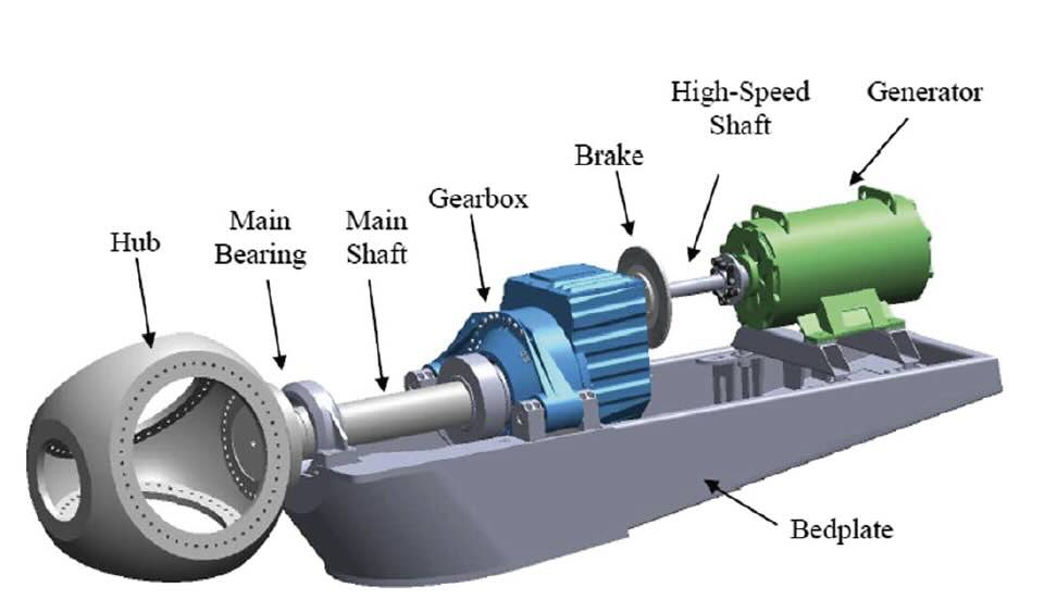 Figure 1. Modular drivetrain configuration of a wind turbine.2
One of the most followed approaches for selecting wind turbine main shaft bearings lubricants is based on kappa. These methods ensure the required contact separation by lubricating film. In oil lubrication, it has been a common practice to recommend a high viscosity lubricant for low-speed applications based on a notion that the lubricating film would otherwise be much thinner.
1 But this approach may not necessarily be the most optimal for greases. As greases generally hold a two-phase (thickener/base oil) structure, it is obvious to expect responses of both thickener and base oil, particularly a thickener dominant lubricating film at low speeds. Such beneficial thickener effects are ignored in the conventional kappa calculation, which is solely based on base oil viscosity.
1 Since the conventional kappa calculation yields an insufficient value for a low viscosity grease (e.g., < 400 cSt) when thickener effects are not considered, users are forced to select greases of high base oil viscosity. This leads to a very conservative way of grease selection for low-speed applications for main bearings in wind turbines.
1 Many OEMs use an alternative way of kappa calculations, which involves a film parameter, as defined in ISO 281—although it has its own limitations. In addition, depending on the turbine manufacturer, turbine model and field experience, the main bearing is either grease or oil lubricated—though the majority are grease lubricated. Despite these inconsistencies, both low and high viscosity greases are in use for main bearing lubrication, and both appear to be working. With the expectation that turbines get bigger, and manufacturers are moving toward high power density solutions, pressure on lubricant concepts and their selection strategies keeps increasing. How might the grease selection for low-speed application change in response to future bigger turbines? What are some possible ways to incorporate thickener effects in kappa calculation? What role will sustainability play in grease selection for wind turbine main bearings? Should more oil lubrication be expected than grease lubrication for main bearings and what drives this?
In this article industry experts share their views on grease selection approaches for wind turbine main bearings, related trends and opportunities for more sustainable operations.
Low viscosities and high viscosities: Challenges and opportunities
Laia Esteban, senior engineer, associate principal engineer, Offshore Wind, GE Renewable Energy, says that when it comes to grease selection processes for wind turbine main shaft bearings, there are some challenges which are mostly rooted in the fact that grease selection is limited to the field experience of technicians. The main bearings from wind turbines, which Esteban has been involved with, are typically lubricated with low viscosity greases. “A bearing’s modified rating life is calculated according to ISO 281 or ISO TS 16281, because with low viscosity greases the resultant aISO factor reduces calculated bearing lifetime,” she says. “Low viscosity greases are penalized because the kappa calculation is based on the grease base oil viscosity and does not consider the grease thickener or additives, although indeed thickener effects should be added into the standards for kappa calculation or measurement according to standardized methodology,” Esteban says. “The effect of the thickener is especially important at low speeds, where main bearings can stay around a 10% (and higher) of their lifetime,” she adds.
STLE member Balasubramaniam Vengudusamy, senior expert tribology, Klüber Lubrication München GmbH & Co. KG, concurs with the previous statement of underestimation of low viscosity greases and not being used widely. He explains: “For wind turbine main bearings greases of two viscosity grades, ISO VG 130 and 300, are typically optimal. However, the industry tends to use ISO VG 460 greases. This grade is selected based on the kappa (κ) requirement of over 1. Kappa is the ratio between the lubricant viscosity and required viscosity for κ = 1.3 There is, however, one downside in this calculation as it only involves the base oil viscosity and, unfortunately, ignores the contribution of thickeners for both viscosity and the resulting lubricant film thickness.
1 The film forming behavior of oils is well explored and reported whereas not much for greases. It is well known that film thickness of oils increases with the speed, following the conventional elastohydrodynamic lubrication (EHL) theory. Being a two-phase system, greases are known to show elastic (thickener) and viscous (base oil) response in film thickness measurements. This was observed almost 25 years ago by Cann
4 and reported that greases form a much thicker film at low to medium speeds and attributed it to thickeners
(see Figure 2).1,4 Some studies also have confirmed this later.”
5-10
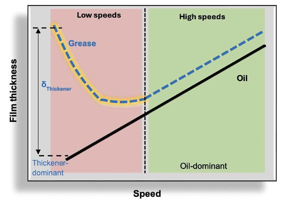 Figure 2. Schematic diagram showing the differences in film thickness between oil and grease, especially at low speeds.1,4
Vengudusamy adds that it can be debated whether the performance of grease can be predicted using its base oil properties like viscosity: “The answer could be yes for high speeds as greases tend to form films like oils at high speeds as their rheology is comparable whereas no for low speeds as the thickener effects are much more significant than the oils
(see Figure 2). When one simply uses base oil viscosity to calculate lambda ratio or kappa, a low viscosity grease would just show a low value and be rejected for its use. But this is not reality as greases (especially low viscosity ones) compared to their base oils form much thicker films at low speeds as shown in Figure 3. Although such beneficial thickener effects in terms of film thickness were reported, this appears not to be practically applied—for instance, in kappa calculation as there are no models available to incorporate the thickener effects. One possible reason could be that greases manufactured by different suppliers may deliver different film forming properties as this largely depends on how greases are cooked and their shear stability. Low viscosity greases have an excellent field record, therefore the conventional way of grease selection using just base oil viscosity is outlived and needs a change.”
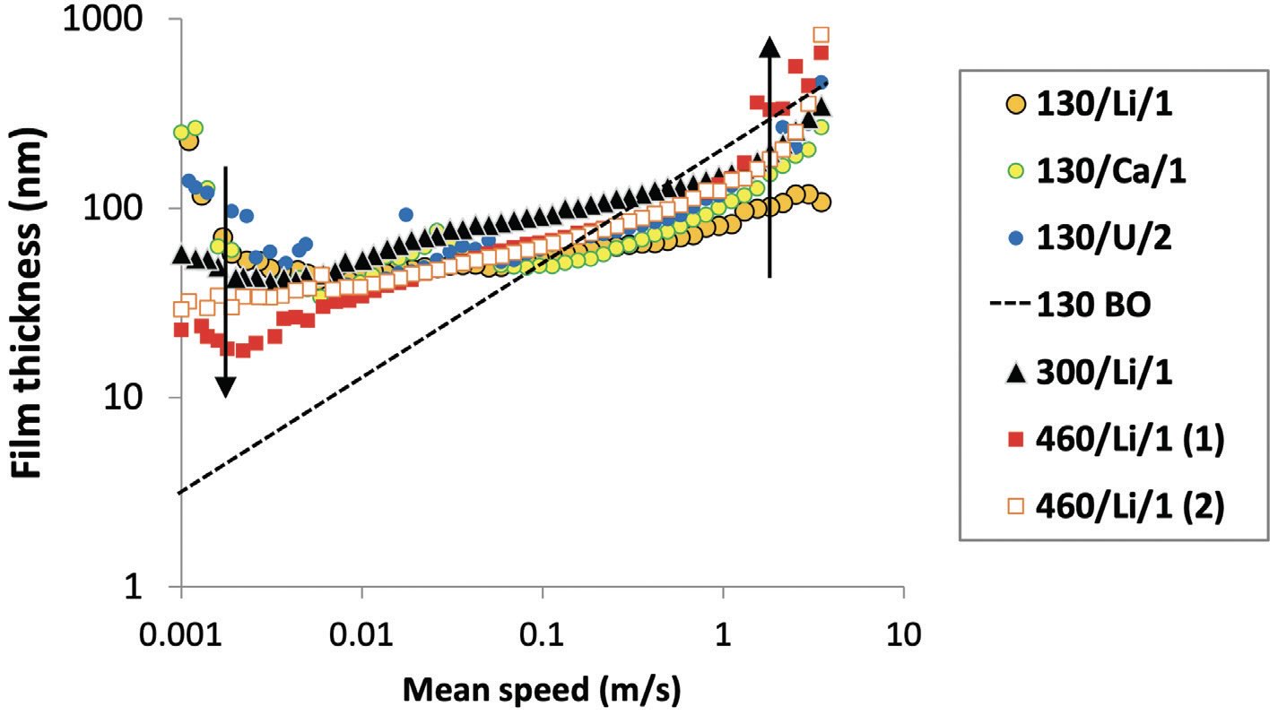 Figure 3. Film thickness measured for different greases at 50 °C using elastohydrodynamic (EHD) 2 rig. Terminology used in legend means this: 130/Li/1 means viscosity at 40 °C (130 cSt), Li means thickener type (lithium, calcium, urea) and 1 means NLGI class (BO is base oil).
Vengudusamy continues: “Other important factors that are less discussed are the contribution of additives, grease distribution, reflow properties and pumpability of greases. Turbines experience a range of transient conditions, involving varying speeds. For instance, very low-speed and standstill regimes require good additives to protect surfaces against wear, corrosion, micropitting and other damages. For example, if the high viscosity greases are claimed to be selected just because they offer higher kappa values, bearings should run without any damages, but there are few field histories that show failures even with high viscosity greases. This tends to suggest that lubrication is not just the base oil viscosity and/or kappa, but instead depends more on the ability of grease to reflow and replenish the contact, its pumpability and additive interactions with the surface. As a rule of thumb, low viscosity greases offer better reflow properties and generate less heat in the bearing than the 400+ cSt greases.”
He adds: “It also may be possible that contamination of bearings during assembly, transport and erection and, in addition, vortex induced vibrations and bearing surface imperfections could compromise the performance regardless of the type of grease used. This may be important to be taken care of more in the future.”
Debottam Bose, wind turbine application specialist with Siemens Gamesa Renewable Energy A/S, expands on reflow properties: “The thickener contributes to the total film thickness by forming a depositing thickener layer on the contacting surfaces as well as by free thickener particles, which enter the contact during operation. For the semi-fluid greases, it is probable that the thickener is more easily available in the contact zone, so there is likely a direct contribution of the thickener to the film thickness for such semi-fluid greases.”
Vengudusamy points out that there are some possible ways to incorporate thickener effects in kappa calculation to enable improvements to the current approach: “One of the ways to incorporate thickener effects in kappa calculation is to use lambda ratio-based kappa calculation (κ = λ1.3) as suggested in ISO 281.
3 The lambda ratio is the ratio between the measured grease film thickness (instead of oil) and the composite surface roughness. Another way is to use the shear viscosity of greases instead of its base oil viscosity to calculate the kappa.
3 Furthermore, it is important to create awareness in the industry about this and engage in discussion with industry experts and certification bodies,” Vengudusamy adds.
Adding on the ways to incorporate thickener effects in kappa calculation, Frédéric Platz, an advanced application engineer and project coordinator, The Timken Co., says: “Some published papers suggest considering an effective lubricant film thickness based on experiments and measurements instead of the one based on base oil viscosity only. This effective film thickness would consider the effect of additives and/or of the thickener. This could then be translated by an adjustment of the bearing lifetime calculation formulas by calibrating the kappa model.” He continues: “An alternative, but not easy to implement, way to adjust the fatigue lifetime predictions is to align the calculation model to bearing life tests. These tests should be as close as possible from the environmental conditions of the bearings in operation and compare the actual life in fatigue to the predicted life for a given low viscosity lubricant. Calibration of the correction factor related to lubrication can then be done to adjust the bearing fatigue calculation model. The challenges of that approach are the limited possibilities to reproduce the field conditions on a rig, the time required to complete such a test which is supposed to simulate 20 or more years of operation and the costs associated to size of the test specimen and all surrounding parts.”
Platz also explains that because these two previously mentioned processes are not yet captured by the international standards like ISO TS 16281, there is a requirement to obtain an approval from certification body, “provided that the owner of the application (turbine OEM), the lubricant supplier and the bearings suppliers are aligned on the method.”
From Platz’s perspective, the challenges faced in the grease selection processes (e.g., with regard to kappa calculation) for the wind turbine main bearings require decades of experience in all market segments where roller or ball bearings are used, the variety of environmental conditions, speeds, loads, temperatures, cleanliness and lubrication conditions. “Understanding lubricant characteristics and testing allow us to better understand product performance relative to bearing function and performance,” Platz says.
He adds: “Our calculation models must take the lubricant characteristics into account to adjust the predicted bearing performance to the grease or oil selection. As some lubricant properties are condition-specific, while bearing calculation models are generic, we can be faced to situations where a discrepancy comes up between projected performance and actual performance. This can be the case for wind main shaft applications, where some lubricants demonstrated good performance on test rigs and in the field after many years of operation, but for which the consideration of base oil viscosity only could underpredict the calculated fatigue lifetime.” He adds: “Thickener and additive properties participate in the lubricant performance but are not taken into account by most of the bearing lifetime prediction models, including ISO TS 16281, which is commonly used by the wind industry. That ISO model will use the kappa calculation by considering only the base oil viscosity at temperature. It can take the effect of extreme pressure additives into account by simplistically forcing kappa to 1.0 when appropriate. The reality is that some lubricants have an effective kappa much higher than the calculated one, and this not only at poor lubrication conditions but also when kappa is greater than 1. As a consequence, the resulting fatigue lifetime calculations can be lower than target while the field experience and the testing demonstrate higher life in fatigue, thanks to appropriate lubrication performance.”
Sriram Jayaraman, a component specialist, mechanical drives, Nordex Engineering & Technology Pvt Ltd, a subsidiary of the Nordex Group, says that the main challenge in lubrication selection for main bearing grease, from his experience, is that the standard method of selection based on base oil viscosity is not a direct indication of the grease performance, due to the low speeds of the main rotor bearing application. “Kappa, which is the basis for lubricant selection, is currently calculated either by base oil viscosity or lubricant film thickness, but in both cases the effect of thickener is not considered. The effects of additives are considered nominally but not in detail. So, there are instances where we see a grease with lower base oil viscosity performs badly in theoretical calculation but performs better in actual application.”
Jayaraman points out: “We should not rely only on the theoretical aspect but test the grease under various conditions to ascertain its performance before using it in the actual application. A standard method should be defined to include the effect of thickener and additive into kappa calculation, to make grease selection for low-speed application more realistic,” he says. There are some possible ways to incorporate thickener effects in kappa calculations. “One possible way is to estimate the lubricant (especially grease) film thickness from test rig for various conditions and plot a curve which can be later used for estimating kappa at required operating condition by the standard formula as defined in standards,” Jayaraman says. “Another method could be to consider effective viscosity of grease, which includes the impact of thickener instead of base oil viscosity for kappa calculation. One of the methods should be standardized in cooperation with certification bodies, bearing and lubricant manufacturers so it becomes part of the standard bearing calculation,” he adds.

Juan Redin, principal key expert mechanical engineer, Siemens Gamesa, shares: “At this moment—and to my knowledge—we do not have adequate transfer equations that can account for the benefits of the thickener’s active duty at low to medium speed. There is some testing conducted by several companies within the industry that show results defining a clear distinction between the kappa’s regime and the thickener’s regime, as well as lubrication persistence or starvation. It would be of general interest to the sector if some reverse engineering could be applied to these and further tests results in order to obtain functional equations as valuable as lambda functions are for oil lubricated bearings—even if they were not to contemplate the instabilities and subtleties of complex deflections.”
Preference of oil versus grease
Typically, greases, not oils, are preferred for wind turbine bearings: “Main bearings operate at low speed a non-negligible amount of time; grease offers higher film thickness at low speeds. The containment of the leakage is more challenging for oil than for greases,” Esteban says.
In Jayaraman’s opinion, both oil and grease have their merits and demerits in terms of grease offering, better handling, better film thickness at low speeds, ease in sealing solutions, better protection against moisture and self-dependent back up system, whereas oil is easy to filter and flush to avoid consequential damages. “So, the selection among them depends on each individual drivetrain concept and should not be generalized. It is feasible that there might be more oil lubricated concepts available in the future compared to the current status quo. This could be further influenced by certain disruptive design concepts like journal bearings for main bearing,” Jayaraman says.
Platz states that lubrication with grease is a common solution for main shaft applications: “It has many advantages especially related to the sealing of the bearings, which is less complex as for oil lubrication. Same advantage concerning the whole system of lubrication, which is much more complex when it is oil lubricated as huge pumps and filtration systems are required. When well distributed, regularly refilled and when the turbine is well programmed to avoid too long static situations, grease is adequate for the conditions of operation during production but also during the special conditions of the turbine (before commissioning, in standstill situations, etc.).”
Platz explains: “Some turbine manufacturers have chosen to use oil lubrication. It becomes mandatory when the gearbox is integrated to the main shaft and both systems share the lubrication. If sealing and circulation are well designed, lubrication by oil also can be an interesting solution with some advantages, like the possibility to control the lubricant temperature, especially in extremely cold environments and when the turbine is stopped during many hours or days.”
Operational challenges
There are some common field problems wind turbines’ engineers face. From Esteban’s experience, these are mainly with grease leakages, grease starvation on manual lubricated bearings due to lack of maintenance and false brinelling (standstill marks). Low viscosity greases offer better behavior against false brinelling since they can flow easier.
On standstill marks, Vengudusamy explains: “Standstill corrosion is a known problem that can be significantly influenced by grease types, including thickener types, additives used, NLGI, oil separation property, base oil viscosity, etc. Under limited motion conditions, the ability of lubricant entraining in the contact plays a vital role in avoiding or reducing the severity of the problem. It is generally believed that low base oil viscosity, good reflow and oil separation properties are potentially important to control standstill corrosion.”
Bose adds, “Standstill marks are an especially relevant concern for offshore turbines; where the machines are getting bigger and the towers are getting higher and slender, standstill marks pose significant challenges. In the case of main bearings in large offshore machines, the problem is often not of classical false brinelling (typically up to 15 micron relative displacement) but more related to ‘galling’ (adhesive wear and distinct material transfer) due to quite larger movement between rollers and raceways.”
For Jayaraman, the most common challenge is to avoid leakage of the lubricant even if lubricant is relatively fluent at operating conditions and harsh environmental conditions. “Another main challenge is ensuring continuous supply of fresh lubricant to the rolling contact instead of aged/used lubricant with degraded properties. Both of these are not only driven by the design of the lubrication system but also the lubricant selection itself. Other issues like wear and micropitting are mostly aggravated by the previously mentioned issues and could be mitigated by addressing the challenges.”
The common field problems Platz encounters are due to the fact that main shaft bearings are calculated for continuous performance in all environmental conditions, whatever the wind and temperature fluctuations. “Unfortunately, the field experience shows that actual bearing lifetime can be significantly reduced, especially for spherical roller bearings (SRBs) in three points-mount arrangement where the single bearing must carry the high loads under lubrication conditions, which are not ideal due to the relatively low rotational speed. This situation could lead to surface damage if the lubricant is not capable of avoiding the metal-to-metal contact. This would evolve in wear issues, with the worn particles going into the lubricant, which aggravates the issue and result to damaged raceway and roller surfaces up to a point where the bearings would be inoperable,” Platz says. “The distribution of lubricant is essential to have the bearings performing well. Unfortunately, the lubrication systems and the lubrication circulation can in some cases be not as efficient as they should be. This would result in the same wear issues as described previously,” he adds.
Redin shares that there also are many challenges on the vast operating scheme of lubrication of a wind turbine’s main bearing set:
•
Contact stress variation and levels.
•
Roller tipping behaviors; stress concentrations.
•
Rolling relative speed: a full scatter from prolonged stand still to slow motion to relatively high speed.
•
Kappa calculation is only one of the factors—one that has its prevalence at medium to high speed—notwithstanding the fact that flowing capacity and potential roller starvation also are relevant at these speed regimes.
•
The lubrication with grease of a large bearing of this kind is performed by flooding, roller pulling and splashing. If the grease does not stick properly or does not resist centrifugal forces or crumbles under its own gravity pull, there is a large chance of starvation of the rollers that are not flooded—the ones in the upper section. These rollers are heavily loaded at scattered load solicitations and on distinctive patterns between the front and the rear bearing.
•
The stiffness matrix of the main shaft arrangement (MSA) also plays an important role on how the bearings are solicited and how much local differentiated deformation there is in between the inner ring and the outer ring. This has consequences on how the roller is able to follow both rings onto the differential deflections. This also has consequences on how the elastohydrodynamic film is formed and preserved, if the relative speed and viscosity allow any to be formed in the first place.
•
A proper and active scheme of additives is very important at the stand still and very low-speed regimes.
•
At low to medium speed, the thickeners’ scheme is key to avoid metal-to-metal contact. There is a large portion of the duty life of a wind turbine at which the kappa value is meaningless.
•
An excessive viscosity does not come for free: it increases rolling and grease breaking-though temperature due to higher flow forces. But it also may make the acquired film more vulnerable and suitable for collapse. A very complex balance of film building versus starvation is more suitable of collapsing with very high viscosity levels (400+ cSt).
•
Mere oil lubrication possesses unsurmountable challenges for these types of bearings, mostly at low speed.
•
There also is the difference between the rolling action of SRB set versus preloaded tapered roller bearing (TRB) set. They are distinctively different but share some common challenges at low-speed regime.
Larger turbines
Since the early 2000s, wind turbines have grown in size—in both height and blade lengths—and generate more energy. Back in 2010, no turbines in the U.S. employed rotors that were 115 meters (380 feet) in diameter or larger. In 2022, the average rotor diameter of newly-installed wind turbines was over 130 meters (~430 feet)—longer than a football field, and almost twice the wingspan of a 747 airplane. Consequently, the lubricant selection for main bearings is changing, too.
Redin outlines some important considerations:
•
It exacerbates the lubricant’s distribution deficiencies.
•
It reduces the rolling speed, because the increment in bearing size will not compensate for the rotation speed reduction.
•
It exaggerates the local aspects of excessive deflections.
•
It exaggerates the already existing challenges related to overall out-of-the-plane bearing deflections.
•
It reduces the efficacy of grease splashing.
•
It reduces the efficacy of roller’s lubricant pulling capacity. The gravity aspect of the force balance, affecting the lubricant stream at the unflooded section, will increase its power over the surface tension or stickiness. Therefore, lubricating the rolling surfaces and the scraping surfaces—even further in this case—will be less effective.
•
The rings of these bearings shall be at the mercy of the stiffness matrix of the MSA. Undulation of the bearing shall be another exaggerated factor. The rollers will be exposed to further cycling load signals due to the large difference of working conditions from one sector to the next or, even more, to the opposite side. The outer ring-roller-inner ring interaction will increase in complexity to the point that the operating experience may not be suitable to predict bearing damage or failure.
Jayaraman shares: “As turbines get bigger, so does the load acting on the rolling contact. Since high load largely influences lubricant film thickness, it might become one of significant parameters for lubricant selection instead of traditional method of only base oil viscosity. Also apart from film thickness, it also is important to evaluate the lubricant for their performance parameters like flowability, pumpability, wear resistance, etc.”
Vengudusamy states that there is a need to optimize lubricant selection for main bearings in the response to turbines getting bigger: “There is an increasing trend of bigger turbines and the loads that such turbines will encounter are projected to be enormously high. There is a common trend toward higher viscosity greases for such future turbines, but this largely depends on the prior experiences of turbine manufacturers with current greases.” He adds: “Reliability of bigger turbine bearings might become a huge topic of interest in the future. Demand for redundant solutions (e.g., rescue/emergency grease, grease with special properties as boosters that can avoid damages) may increase. The current approach of one-time grease filling and expecting 25 years of life may change and require intermittent on-demand corrective solutions or measures (e.g., flushing old grease out and adding boosters to enhance lifetime). More and more condition monitoring may evolve to constantly monitor the health of the bearing and grease and take corrective measures as needed.”
Platz concurs with the previously mentioned: “The bigger size of the turbines implies bigger size of the components, including the main shaft bearings. The volumes and weights are then even more affected by the upscale and so are the surfaces to protect and to lubricate. The lubricant distribution within the bearing is therefore a key parameter. Not all the lubricants, especially when it is grease, are equal regarding distribution. Any dry surface from the rolling contact area might deteriorate at early stage, which would result in lower bearing lifetime. And even in non-rolling contact area, surfaces must be protected against rust in the presence of water.” Platz adds: “Antiwear and anti-fretting also are characteristics which become more important when the contacting surface becomes bigger and bigger; this concerns contacts between rolling elements and races or shoulders, or between rings and countersurface. The lubricant must, in addition, perform in a large range of temperatures, from very cold to quite high.”
Sustainability
Sustainability concerns already start to play an important role in grease selection. Vengudusamy says: “Many turbine manufacturers have set their sustainability goals, for example zero emission turbine or carbon free target. Lubricant is part of this so it must contribute to achieving the global target.” Additionally, he states that there is a significant shift in both grease formulation and selection process because of the widespread sustainability goals in the industry. Although the switch to biolubricants offers significant benefits particularly for offshore application, this may not happen anytime soon. This firstly is because the process to get a grease approved for this application is massive and it may take at least five years to see such sustainable lubricants used in main bearings. “There is a general understanding that the number of bio-additives available is generally limited as compared to conventional additives. This also may delay the grease formulation,” Vengudusamy states. “Under the aspect of the entire lifecycle of a turbine, not only the biodegradability of a lubricant but also the CO
2 emission during manufacturing, waste production and the use of renewable raw materials should be considered,” he adds.
Esteban says: “Wind turbines are getting bigger over the years and, as a consequence, bigger bearings are needed and a higher volume of grease to lubricate is then needed, too. Wind turbine main bearings need around 100 kg of grease per year per wind turbine. For that reason, I think we need to go to biodegradable greases or to explore ways to clean and reuse the used grease,” she adds. In the future, “sustainability will lead the grease selection,” Esteban states.
Jayaraman concurs: “Going forward it is quite possible that recycling of the used lubricant may play a crucial role in lubricant selection to ensure sustainability. It also is very important the lubricant is free of any harmful substances that affect health and safety of personnel handling the lubricant and the environment.”
Summary
Wind turbines, a sustainable energy source, are known as a green technology that minimize the carbon emission into environment. Considering the rapid technological growth and increasing demand for greener solutions, it is important to continue to look for innovative lubricants in order to achieve as low friction as possible to maximize the efficiency and lifetime of units. However, as industry experts share in this article, many challenges exist due to the lack of in-depth knowledge related to greases used in bearings of wind turbines. Thus, a holistic understanding of the grease tribosystem in the application is critical in order to ensure that greases used in wind turbine main shaft bearings deliver the best performance, prevent premature failures and deliver energy savings.
REFERENCES
1.
Vengudusamy, B. et al. (2019), “On the film forming and friction behaviour of greases in rolling/sliding contacts,”
Tribology International, 129, pp. 323-337.
2.
Mandic, G., Nasiri, A., Muljadi, E. and Oyague, F. (2012), “Active torque control for gearbox load reduction in a variable-speed wind turbine,”
IEEE Transactions on Industry Applications, 48 (6), pp. 2424-2432.
3.
DIN: ISO 281:2010-10, Rolling bearings – Dynamic load ratings and rating life (ISO 281: 2007).
4.
Cann, P.M. (1999), “Starved grease lubrication of rolling contacts,”
Tribology Transactions, 42 (4), pp. 867-873.
5.
Cen, H., Lugt, P.M. and Morales-Espejel, G. (2014), “Film thickness of mechanically worked lubricating grease at very low speeds,”
Tribology Transactions, 57 (6), pp. 1066-1071.
6.
Morales-Espejel, G., Lugt, P.M., Pasaribu, H.R. and Cen, H. (2014), “Film thickness in grease lubricated slow rotating rolling bearings,”
Tribology International, 74, pp. 7-19.
7.
DeLaurentis, N., Kadiric, A., Lugt, P. and Cann, P. (2016), “The influence of bearing grease composition on friction in rolling/sliding concentrated contacts,”
Tribology International, 94, pp. 624–632.
8.
Vengudusamy, B., Kuhn, M., Rankl, M. and Spallek, R. (2016), “Film forming behaviour of greases under starved and fully flooded EHL conditions,”
Tribology Transactions, 59, pp. 62-71.
9.
Kanazawa, Y., Sayles, R.S. and Kadiric, A. (2017), “Film formation and friction in grease lubricated rolling-sliding non-conformal contacts,”
Tribology International, 109, pp. 505-518.
10.
Goncalves, D., Vieira, A., Carneiro, A., Campos, A.V. and Seabra, J.H.O. (2017), “Film thickness and friction relationship in grease lubricated rough contacts,”
Lubricants, 5 (34), pp. 1-16.
Dr. Yulia Sosa is a freelance writer based in Peachtree City, Ga. You can contact her at dr.yulia.sosa@gmail.com.