Automotive transmissions
By Dan Holdmeyer, Contributing Editor | TLT Lubrication Fundamentals March 2024
The transmission allows the engine to operate efficiently by varying outputs of speed and torque.
Mechanical work is defined by the force required to move an object, times the distance the object is moved, or force times distance. In other words, no work is accomplished by pushing against a wall without moving it, but pushing a car along a city block is work. Less work is required to push a car a city block with a slight downhill grade because gravity reduces the force required to move the car. Conversely, more work is required to push the car back up the block.
Mechanical power, often called horsepower, is a measure of the rate work is done, or work divided by time. It takes more power to move an object faster than to move it slowly. Thus, race cars generally have larger, or more powerful, engines than your average vehicle of the same weight. Race car engines produce their maximum horsepower at high revolutions per minute (rpm), somewhere between 5,000-10,000 rpm, or even higher, whereas the average car engine operates between 1,500 and 3,000 rpm. The maximum power efficiency is a narrower range within those rpm ranges for each engine.
So, what does a transmission have to do with that? The transmission in a motor vehicle allows the engine to operate at its maximum power efficiency, within that relatively narrow range of rpm. A transmission provides various outputs of speed and torque from a given input of speed and torque, or horsepower. (Torque is converted to work via the car’s driveshaft, differential, axles and wheels to move the car.) In first gear the output speed is low, but the torque is high, enabling the engine to operate near its power efficient rpm to take the car from stop to a certain miles per hour (mph). Second gear, where the output speed is higher and torque is lower than first gear, keeps the car moving in the next higher mph range while the engine is in its power efficient rpm range. Third gear is for the next mph range, and fourth gear is for the next mph range, and so on, keeping the engine in or near its maximum power efficiency range. The specific engine efficiency range, horsepower, targeted operating speed and vehicle weight are only some of the variables that go into determining the optimum number of transmission gears and actual gear ratios for each vehicle.
There are five major categories of transmissions commonly used in automobiles today: manual, dual-clutch, automatic, continuously variable and electrified.
Manual transmissions transfer power via a gear train through the unit (see Figure 1). The input shaft drives a gear that engages with another gear on a countershaft in the transmission. Another gear on the countershaft engages and drives a fourth gear on the output shaft. Gear ratios are changed when the gears slide along their respective shafts to disengage and engage with other gears. For reverse, an idler gear is used to reverse the output shaft rotation with the appropriate gear ratios. The gears can be either spur or helical.
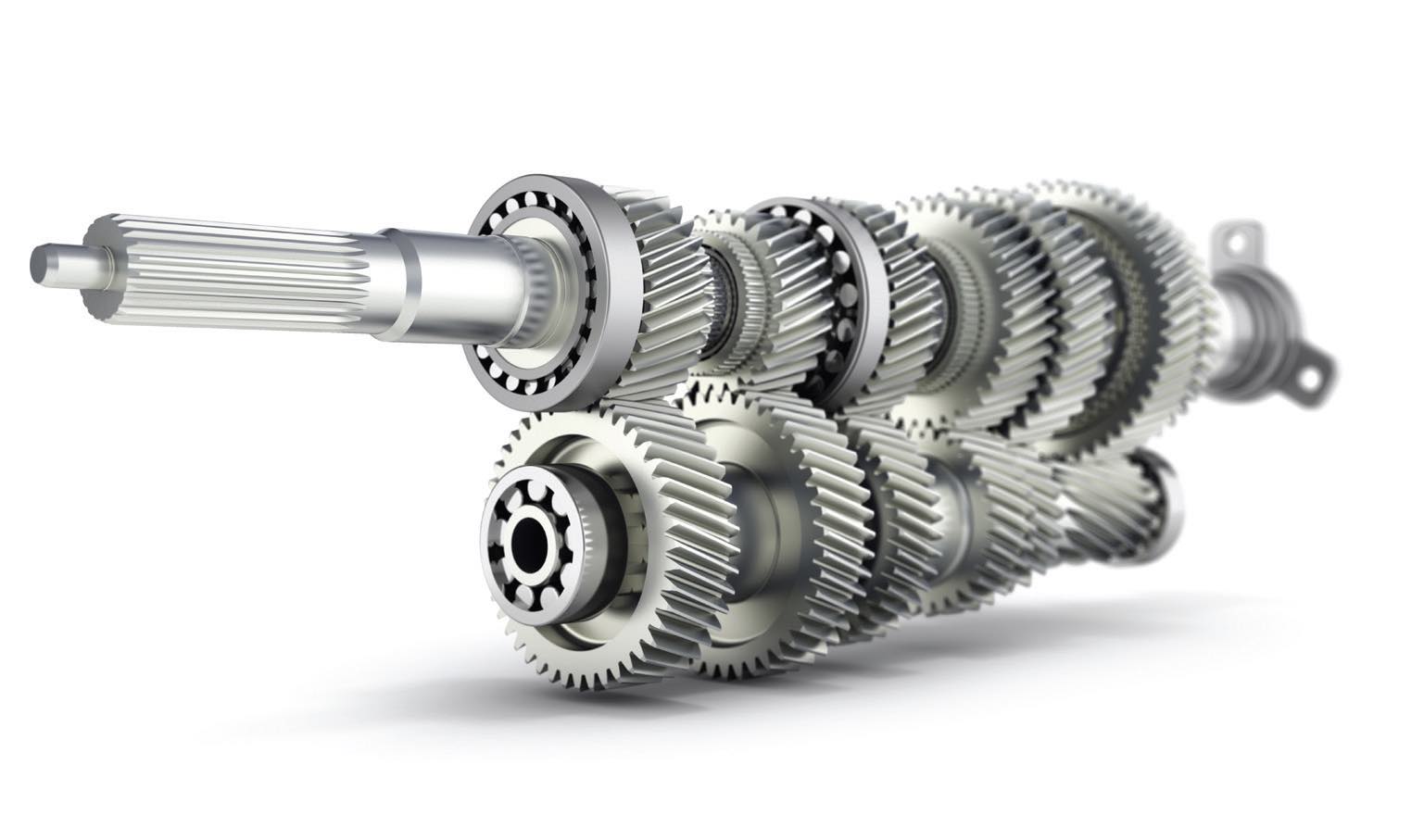
Figure 1. Manual transmission.
A gear shifter in the passenger cabin of the vehicle links to shift forks within the transmission. The forks slide together the appropriate gear engagements for the gear selected by the driver. My first manual transmission gear shifter was located on the steering column just forward of the steering wheel. It was a three-speed transmission and was referenced as “three on the tree.” My next manual transmission was a “four on the floor,” referring to a fourspeed transmission with the gear shifter located on the floor.
“Synchronizers” in manual transmissions synchronize the speed of, and align, the to-be engaged gears so their teeth slide together without “grinding” the gears. Grinding refers to the noise and wear that happens when two gears moving at different speeds are pushed together until they finally do, or don’t, mesh and fully engage. Synchronizers employ friction to bring the meshing gears to the same speed and are usually made of copper alloy.
Many manual and dual-clutch transmissions today do not actually slide the internal gears but slide gear selectors. The gear selector is engaged with the shaft and slides to mesh with the appropriate gear, so the gear then is engaged and can transfer power via shaft. Synchronizers are still used to help bring the gear selector and shaft speed to align and engage its internal gear teeth with the selected gear.
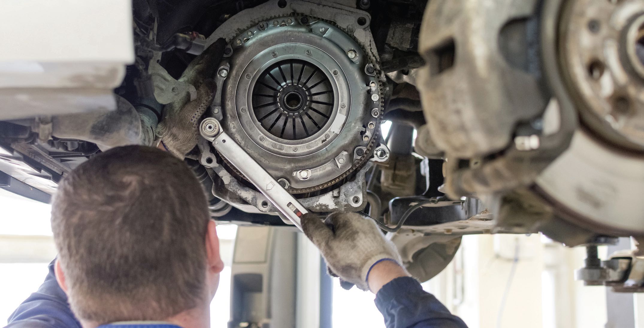
Anyone that has driven a manual transmission knows that when the gears are engaged under load, meaning transmitting power through them, they cannot be easily disengaged. Therefore, the clutch pedal in the driver’s compartment is depressed to disengage a dry clutch between the transmission and engine and stop the transfer of power from the engine. The open clutch is also necessary to enable stopping the vehicle, with the brakes, while the engine is still running. It is called a dry clutch because it is not inside the transmission exposed to any lubricant.
Dual-clutch transmissions transfer power on a similar gear train principle as the manual transmission, except the dual- clutch transmission has two gear trains and two clutches. The operation is more like an automatic transmission, as electronics, not the driver, control the gear selection and clutch engagements. The dual clutches can either be external dry clutches or internal (inside the transmission housing) wet clutches, cooled by the transmission fluid. The input shafts are concentric, one inside the other, as are the clutches. Each clutch engages and disengages its specific input drive shaft. Each drive shaft engages with its own countershaft to provide the various gear ratios that ultimately drive a single output shaft. This configuration allows for a gear ratio to be engaged on one of the drivetrains and to transfer power while a second gear ratio is synchronized on the other drivetrain. This second gear ratio starts transmitting power when its drivetrain clutch is engaged, and the first drivetrain’s clutch is disengaged so a third gear ratio can be synchronized on that drivetrain, ready to transmit power. The dual-clutch transmission speeds the transition from one gear to the next providing improved efficiency over the manual transmission.
An automatic transmission (see Figure 2) gets engine power via a torque converter versus a clutch managed by the driver, or dual clutches managed by electronics, for the manual and dual-clutch transmissions, respectively. The torque converter is a fluid coupling that allows the engine to rotate at low rpm without driving the transmission, although the car may “creep” along with the engine at idle, the transmission in drive, and no braking is applied. Fluid flows from the turbine, the front portion of the torque converter driven by the engine, through a stationary stator, to impeller blades that then drive the pump and transmission. Once the vehicle reaches speed the torque converter locks up, no longer hydraulically connected but mechanically connected to and driving the transmission in overdrive.
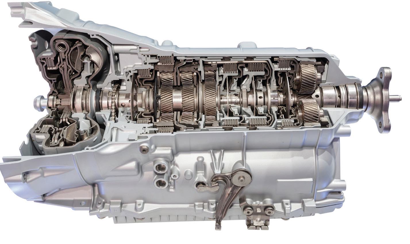
Figure 2. Automatic transmission.
Gear ratio changes are done by clutch packs, brake assemblies and planetary gearsets (see Figure 3), all controlled by a hydraulic valve body in the transmission. An internal pump generates hydraulic pressure for the valve body. Specific clutch packs and brake assemblies are activated to hold and release predetermined combinations of sun, planetary and ring gears of an in-line series of planetary gearsets that provide various gear ratios from the transmission input to output.
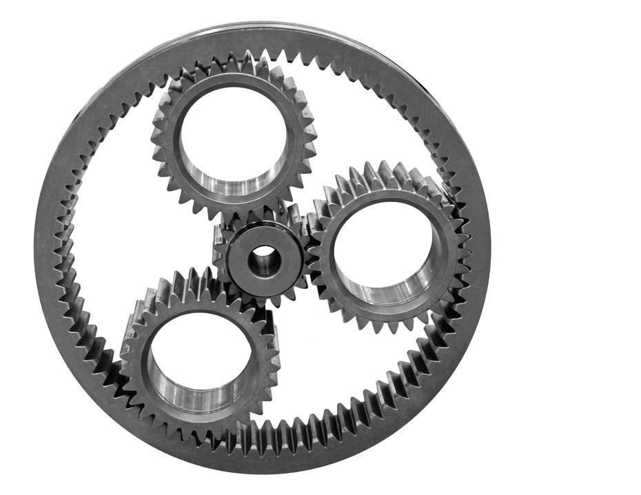
Figure 3. Planetary gear assembly.
Continuously variable transmissions (CVTs) are commonly composed of three main components: a drive pulley, a driven pulley and a steel belt or chain (see Figure 4). The drive pulley is connected to the engine via a torque converter, or sometimes with an electronic clutch, or centrifugal clutch. The driven pulley is connected to the transmission output. The input to output speed ratio is, as the name implies, continuously variable; there are no “steps” in the output versus input ratio as the transmission transitions from low to high output speed.
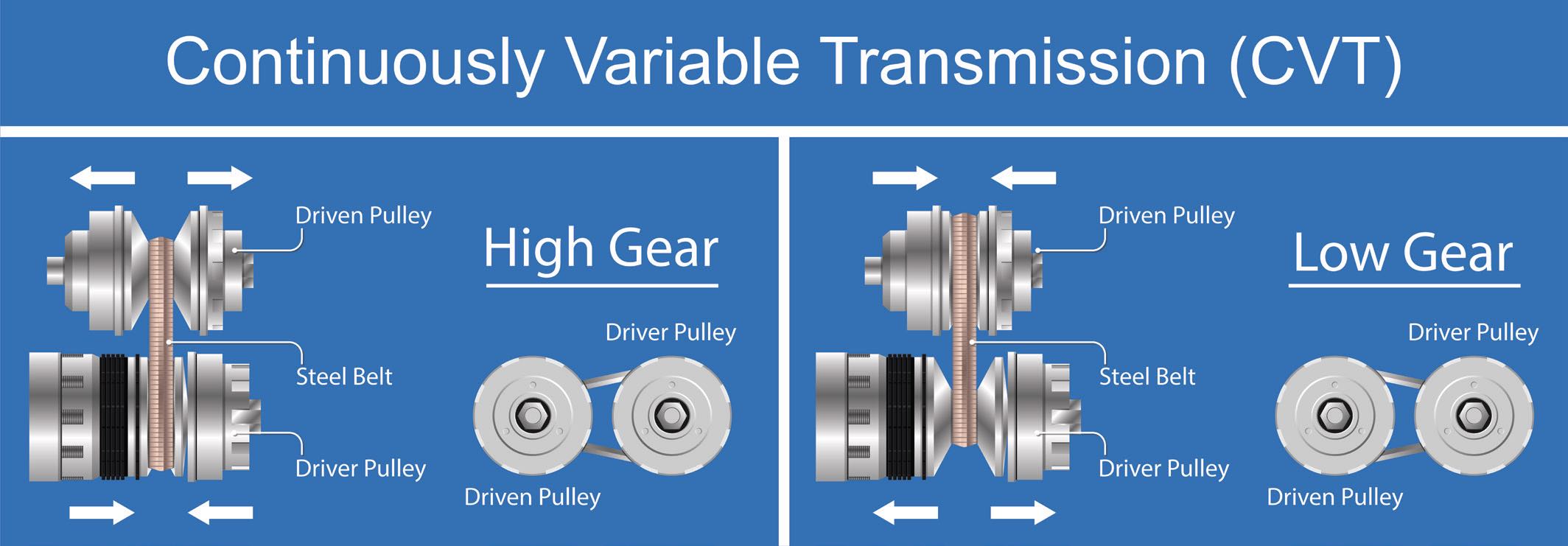
Figure 4. Continuously variable transmission.
The transmission operates on a variable diameter pulley system. Each pulley has two angled cones that face each other. The chain, or the steel belt, rides in the groove between these cones. The groove diameters of the cones are changed by moving one of the cones on each pulley closer or farther away from the opposing cone. One cone on each pulley must not slide axially so the belt or chain remains aligned. Additionally, as one pulley’s cones come together the other pulley’s cones must separate to maintain proper tension on the belt or chain.
The groove diameter is greatest when the cones are closest together. So, if the driving pulley cones are separated completely within their range and the driven pulley cones are close together, the transmission output speed would be low, i.e., in first gear. If the driving pulley cones are close together, and the driven pulley cones are separated as far as mechanically allowed, the output speed would be high with low torque. One can imagine the infinite number of different gear ratios possible between these two extremes— continuously variable.
Electrified versions of the previously discussed transmissions may be required in hybrid vehicles particularly when the e-motor is at the transmission input or output with intermittent power contribution. In the case of the power split hybrid, a dedicated hybrid transmission is required. The transmission needs to avoid conflicts with different power inputs from the engine and e-motor. Significant research and development is ongoing with hybrid vehicle requirements.
Battery or fuel cell electric vehicles have their e-motors at the drive axle or the individual drive wheels and do not require a transmission, as they are generally single speed for passenger cars.
Dan Holdmeyer is retired from Chevron Lubricants and is based in Washington, Mo. You can reach him at dan.holdmeyer@gmail.com.