Meet the Presenter
Dive into the world of wear with this article, based on the webinar entitled Wear Mechanisms and the Relations of Microstructure and Wear in Metals. Hosted by the American Society of Mechanical Engineers' (ASME) Tribology Division and presented by Dr. Stefanie Hanke on Aug. 24, 2022, the session explored metal wear mechanisms in depth. Courtesy of STLE, this article captures the core insights from this ASME-organized event. For more technical content from the ASME Tribology Division Webinar Series, visit the ASME Tribology Division's website at www.asme.org/get-involved/groups-sections-and-technical-divisions/technical-divisions/technical-divisions-community-pages/tribology-division.
Dr. Stefanie Hanke is a researcher in materials science in mechanical engineering. After receiving her doctorate degree, she was a group leader at Helmholtz Center Geesthacht, Germany. While studying the effect of thermo-mechanical treatment on tribological behavior of alloys, she accomplished the first in situ study of phase transformations in titanium alloys during friction surfacing using synchrotron radiation. Today, she is head of the chair of Materials Science and Engineering at the University of Duisburg-Essen, Germany, focusing on microstructure, mechanisms of damage accumulation and failure initiation in metals in fatigue and tribology.
You can reach her at stefanie.hanke@uni-due.de.

Dr. Stefanie Hanke
KEY CONCEPTS
•
Four types of wear mechanisms can affect materials.
•
Microstructure modification by friction surfacing on wear behavior of Al alloys with different Si contents has a positive effect.
•
The process of friction surfacing offers a possibility to generate coatings from Cr60Ni40 alloy with less deformation and smaller disruptions, and wear rates versus cast materials.
This article covers the topic of wear mechanisms and their classification. It also covers microstructure, mechanisms of wear and how they affect materials. It reviews the modern understanding of the influence of microstructural elements and the physical properties of materials wear. The first part describes the relation between microstructure and mechanical properties of materials and discusses wear types such as abrasion, adhesion, surface fatigue and tribochemical reactions. The second part covers friction surfacing (FS) and thermomechanical processing by FS of aluminum silicon (AlSi) alloy and chromium nickel (CrNi) alloy.
This article is based on a webinar presented by Dr. Stefanie Hanke, researcher in materials science in mechanical engineering, and the Tribology Division of the American Society of Mechanical Engineers (ASME) titled Wear Mechanisms or the Relations of Microstructure and Wear in Metals. See Meet the Presenter for more information.
Wear mechanisms
There are four groups of wear mechanisms
(see Figure 1): tribochemical reactions, surface fatigue, abrasion and adhesion. Typically, under normal standard conditions, when tribochemical reactions are dominating, the wear rates are generally low, but when there is a severe adhesion wear rates are rather high. Wear groups also can act simultaneously and in different severities, thus creating a different wear trend.
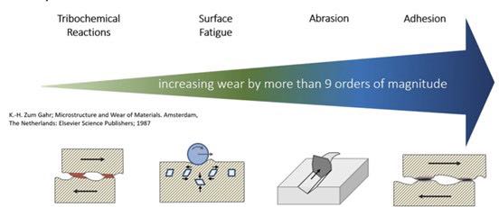 Figure 1. Steady state wear mechanisms.1
Tribochemical reactions
Tribochemical reactions are the formation of chemical reaction products as a result of chemical interactions between the elements of a tribosystem initiated by tribological action
(see Figure 2).1
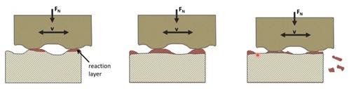 Figure 2. Wear mechanisms – tribochemical reactions.1
In tribochemical reactions, chemical reactions take place involving materials of two contacting bodies, the surroundings and possibly a lubricant or other media if present. When the wear is dominated by this mechanism, the products of reaction form a layer on top of the surface of one or both bodies, which causes these layers to grow in thickness and eventually fracture. The parts break off which is how wear occurs.
What’s specific about tribochemical reactions is that these reactions are not normal chemical reactions that would occur with the same substances in the same environment without a tribological load. There also is frictional heating and many other effects taking place that can accelerate the wear.
Figure 3a shows an image recorded by scanning electron microscopy of a worn surface; some darker surface regions are observed, and these are tribochemical reactions. Figure 3b shows light microscopic images of the typical appearance of tribochemical reaction layers that form on steel.
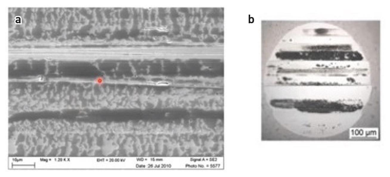 Figure 3. Wear mechanisms – tribochemical reactions.
Surface fatigue
Surface fatigue is fatigue and formation of cracks in surface regions due to tribological stress cycles that result in the separation of materials, e.g., pits.
1
Surface fatigue involves cyclic loading and damage that is brought by an initiation and propagation of cracks
(see Figure 4). In contrast to normal fatigue, these cracks do not lead to a fracture of a whole component, but instead they lead to small breakouts on the surface, initiating wear.
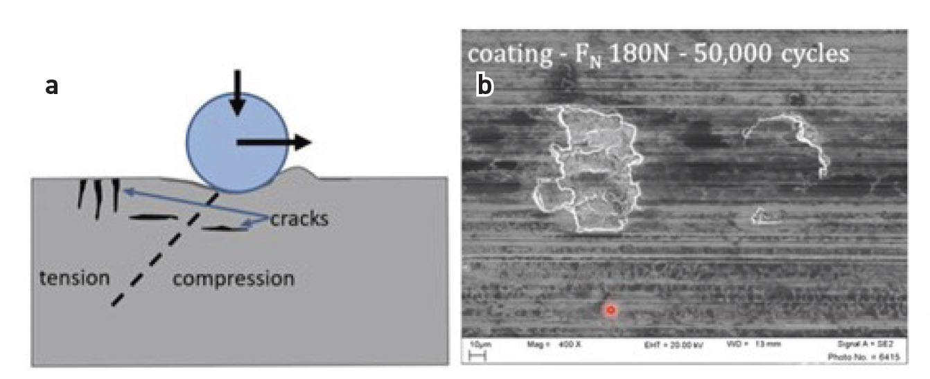 Figure 4. Wear mechanisms – surface fatigue.
The cracks which are under surface fatigue
(see Figure 4a) can initiate and grow from the surface, or below the surface where they are not visible. As they become larger, they eventually reach the surface in each case, and such large delamination forms as can be seen in Figure 4b. In addition, tribochemical reaction layers can be seen here as well, which means that there are two different groups of wear mechanisms present simultaneously.
Abrasion
Abrasion is the removal of materials due to scratching
(see Figure 5).
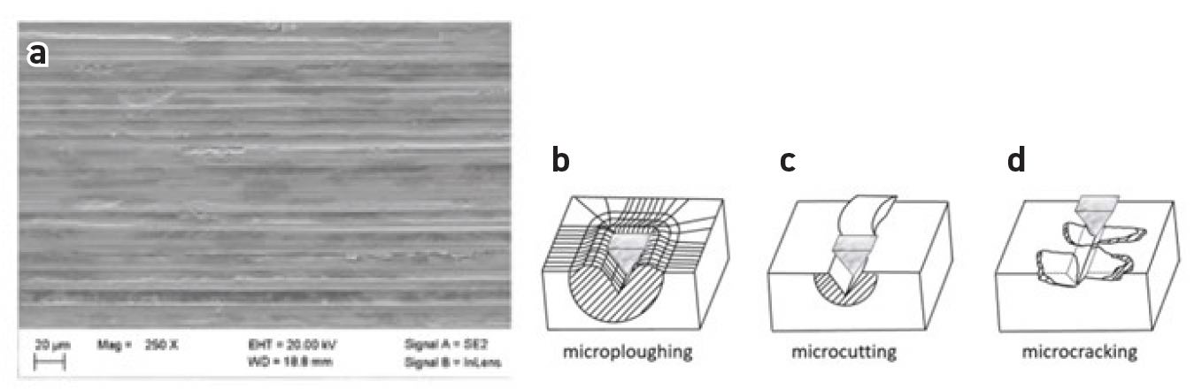 Figure 5. Wear mechanisms – abrasion.1
During abrasion
(see Figure 5), the surface that is undergoing an abrasion can result in a rather wide range of wear rates because abrasion happens in different severities. In addition, there are some sub-mechanisms of abrasion: microploughing, microcutting and microcracking.
Adhesion
Adhesion is the formation and breaking of interfacial adhesive bonds, e.g., cold-welded junctions.
Like other wear mechanisms, adhesion also can lead to severe wear. Adhesion takes place on a surface and contacting surfaces. It can occur in combustion engines, where a lot of funnel op damage occurs in motors, and masses are distributed due to volume losses. Figure 6 shows the side of the surface where material adheres and has a buildup material from the other side. This creates a roughness on the sliding surface.
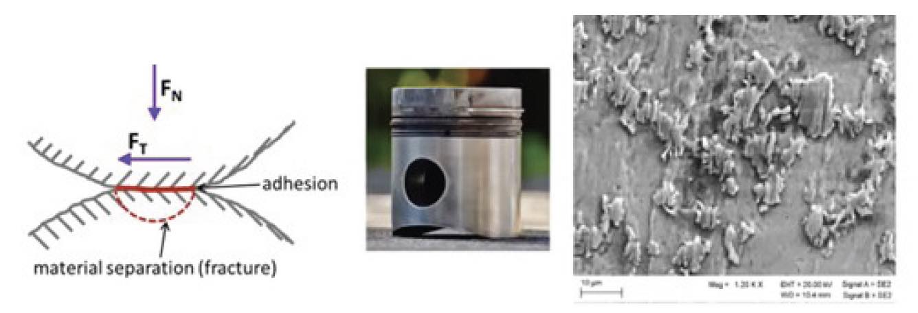 Figure 6. Wear mechanisms – adhesion.
Typical measures against the previously discussed wear mechanisms are as follows:
Tribochemical reactions
•
Typically no problem, low wear rates
•
Except for high-temperature wear, electrical contacts
•
Use noble metals or ceramics, avoid oxygen
Abrasion
•
High hardness helps against grooving by counterbody
•
Hard phases are helpful, too
•
Careful: high hardness -> high brittleness
Surface fatigue
•
Increase fatigue resistance
•
Careful: high hardness -> high brittleness
•
Very hard materials are prone to experience surface fatigue
Adhesion
•
Wide range of wear rates; depends on dimensions of cold welds
•
Plasticity of (microscopic) contact spots precede cold welds -> hardness/strength helps
•
Use dissimilar materials.
Wear testing
Figures 7a and 7b show two wear tests. Figure 7a is a sliding wear, ballon- plane configuration. The ball slides over the plane surface in a reciprocating motion. Figure 7b shows the ultrasonic cavitation test, which is described in more detail in the standard ASTM G32-16.
2
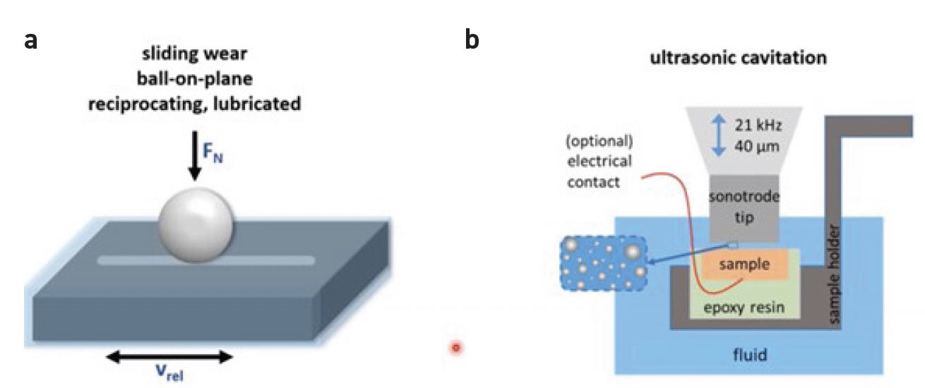 Figure 7. Wear testing.
This is a simplified laboratory test, which is based on ultrasonic oscillations. Dissolved gases in fluids are the cause for wear caused by cavitation. In real applications, when the pressure of the fluid decreases, it is typically due to an increase in the flow speed. The flow speed increases, the pressure drops, and if the pressure drops enough to meet the solubility limit of the dissolved gases, bubbles will form. When these bubbles move with the fluid, they eventually will reach a region with higher pressure and then they will collapse again, and this collapse is very violent for surfaces. It’s very fast, and it emits shock waves, pressure waves and small water jets. When this happens close to a solid surface, it can severely damage the surface.
Friction surfacing
Friction surfacing (FS) is generally used to apply metal-based coatings in a solid state, i.e., without bulk melting the material being deposited.
3
The process shown in Figure 8a starts with a stud of the coating material. Its face is pressed with a defined axial force onto the substrate to be coated, while the stud rotates around its longitudinal axis. Frictional heating occurs in the contact, and the temperature of the material increases until the stud face adheres to the substrate. The rotational motion of the stud no longer occurs at the interface with the stationary substrate but, rather, by plastic flow within a shear plane in the thermally softened material in the stud tip. This soft, plastically deforming stud material is often referred to as a “quasi-liquid layer” or shear zone. A transverse motion is superimposed by moving the machine table on which the substrate is clamped. Along the path, some of the softened material is deposited from the stud tip onto the substrate, leaving a coating with a width similar to the stud diameter
(see Figure 8b).3
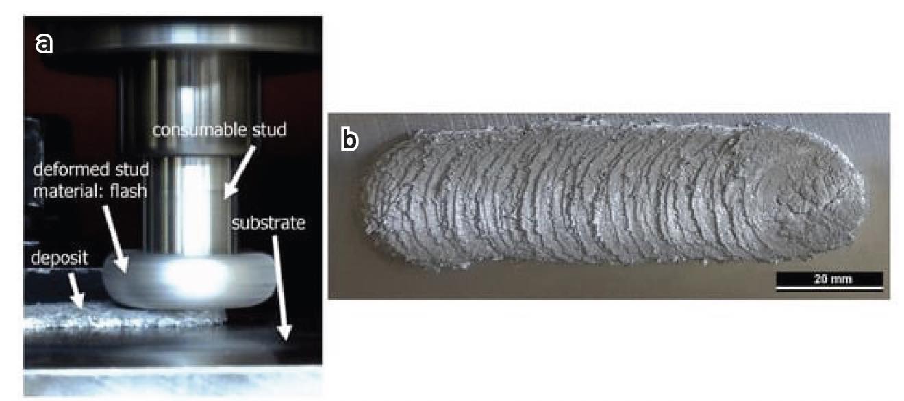 Figure 8. (a) FS process and (b) photograph of an FS deposited coating from an Al alloy with 14.6% Si.
Thermomechanical processing by FS: AlSi alloy
Three Al-base alloys with different Si contents were studied. Due to the comparable amounts of alloying elements—apart from Si—it is assumed in this study that the influence of the intermetallic phases is similar in all alloys. Al cast alloys are used commercially in vehicle construction, which are used for, e.g., cylinder heads, engine, chassis components, etc. In order to exclude influences of other alloying elements on both the FS processing characteristics and on the wear behavior of the materials, customized AlSi alloys were produced in which only the Si content was adjusted following commercially available applicable alloys.
3
Hypo- and hypereutectic AlSi alloys with 6.6%, 10.4% and 14.6% Si were deposited as thick coatings by FS, resulting in grain refinement and spheroidization of needle-shaped eutectic Si phase
(see Figure 9).3 These alloys were investigated for sliding wear behavior in the original state (green bars) and also coated (blue bars)
(see Figure 9). After the alloys had undergone thermomechanical processing during FS deposition, wear rates were analyzed under different testing conditions.
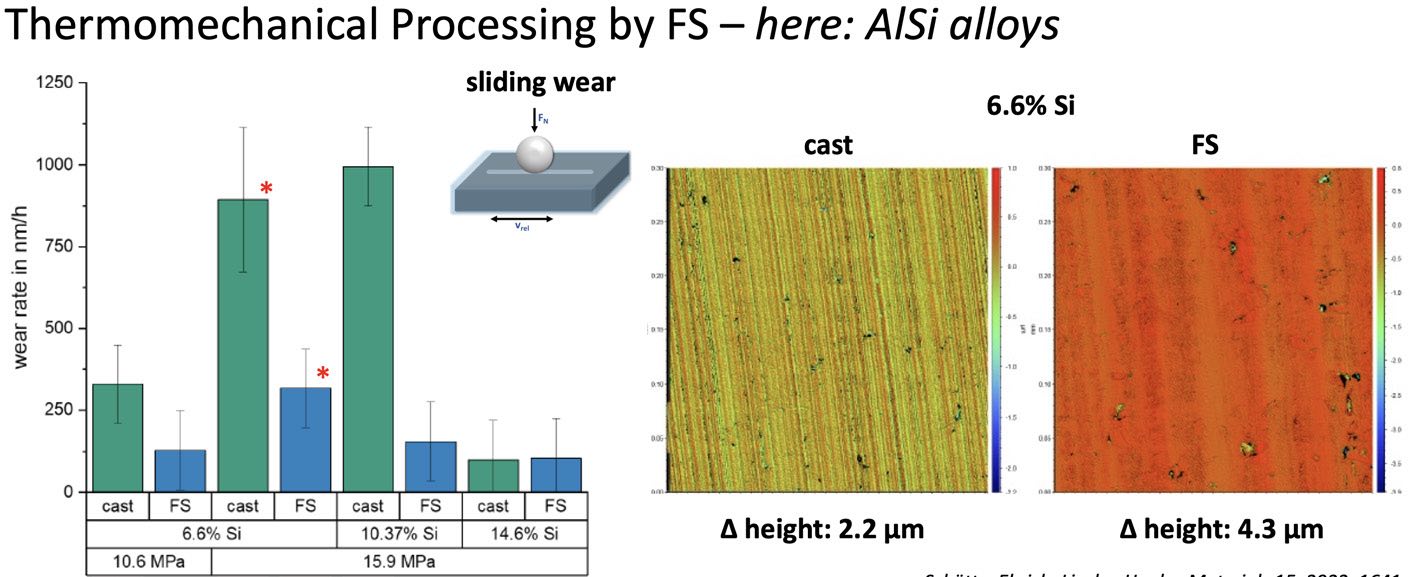 Figure 9. Wear rates (weight loss) at end of tests with different contact pressures (10.6 MPa and 15.9 MPa), for the three alloys (6.6%, 10.4% and 14.6% Si) in FS and as-cast state.3
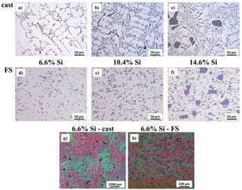 Figure 10. Light microscopic figures showing the microstructure of the Al alloys. As-cast state: (a and b) hypoeutectic, Si needles; (c) hypereutectic, Si needles, Si primary phase particles. FS coatings: (d and e) hypoeutectic, fine dispersed Si particles; (f) hypereutectic, fine dispersed Si particles, Si primary phase particles. After electrolytical etching observed under polarized light 6.6% Si alloy: (g) as-cast-coarse grain size, (h) FS coating-fine-grained recrystallized microstructure.3
Figure 10 shows the microstructure of the three processed Al alloys in an as-cast state and after deposition as FS coatings as shown in Figure 5. In the as-cast state, Si nee- dles dominate the microstructure in the two hypoeutectic alloys
(see Figure 10a and 10b), while the hypereutectic alloy additionally contains bulky primary Si phase particles
(see Figure 10c). After FS deposition, the Si needles have largely transformed into finely dispersed, almost spherical Si particles, while the bigger primary Si particles in the hypereutectic alloy remain almost unchanged
(see Figure 10d and 10e). The grain structure can be observed after etching using polarized light. The grains in the Al alloy with 6.6% Si in an as-cast state and after coating deposition are shown in Figure 10g and 10h. Grain refinement through dynamic recrystallization by a factor of approximately 20 is clearly observable. The average grain size for the 6.6% Si alloy in the as-cast state is (440.8 ± 117.52) μm and in the FS state (20.8 ± 2.1) μm (determined by linear intercepts method according to DIN EN ISO 643).
3
Lubricated sliding wear tests were performed on a pin-on-disc tribometer using AlSi alloys in as-cast and FS-processed states as pins against 42CrMo4 steel discs. The chemical composition of the worn surfaces was analyzed by X-ray photoelectron spectroscopy (XPS). The wear mechanisms were studied by scanning electron microscopy (SEM) and focused ion beam (FIB), and the wear was evaluated by measuring the weight loss of the samples. For the hypoeutectic alloys, spheroidization of the Si phase particles in particular leads to a significant improvement in wear resistance. The needle-shaped Si phase in as-cast state fractures during the wear test and small fragments easily detach from the surface. The spherical Si phase particles in the FS state also break away from the surface but to a smaller extent. No reduction in wear due to FS was observed for the hypereutectic alloy. Large bulky primary Si phase particles were already present in the cast state and didn’t change significantly during FS, providing high wear resistance in both material states. It highlights the mechanisms and limitations of improved wear resistance of Si-rich Al alloys deposited as thick coatings by FS.
3
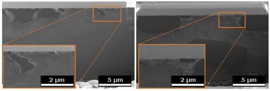 Figure 11. SEM figures of FIB cross sections in worn surfaces of the pins with 10.4% Si: (a) as-cast, (b) FS.3
Figure 11 shows SEM figures of FIB cross sections of 10.4% Si pins, recorded underneath the worn surfaces. In the FS state, the Si phase particles (appearing dark in these figures) have a rounder shape, and the material around them displays a thin, strongly deformed layer. The Si particles in the cast state have retained sharp edges, and a pronounced deformation of the surrounding material can be seen. In addition, the Al between the Si particles displays heavy deformation in the subsurface material, with a locally varying depth of up to ≈ 500 nnmm.
3
In summary, by changing the morphology of the silicon particles, without changes to the chemistry nor hardness, the wear rate decreases by more than 50% for 6.6% and 10.4% silicon. For the higher silicon content, the effect is not significantly visible.
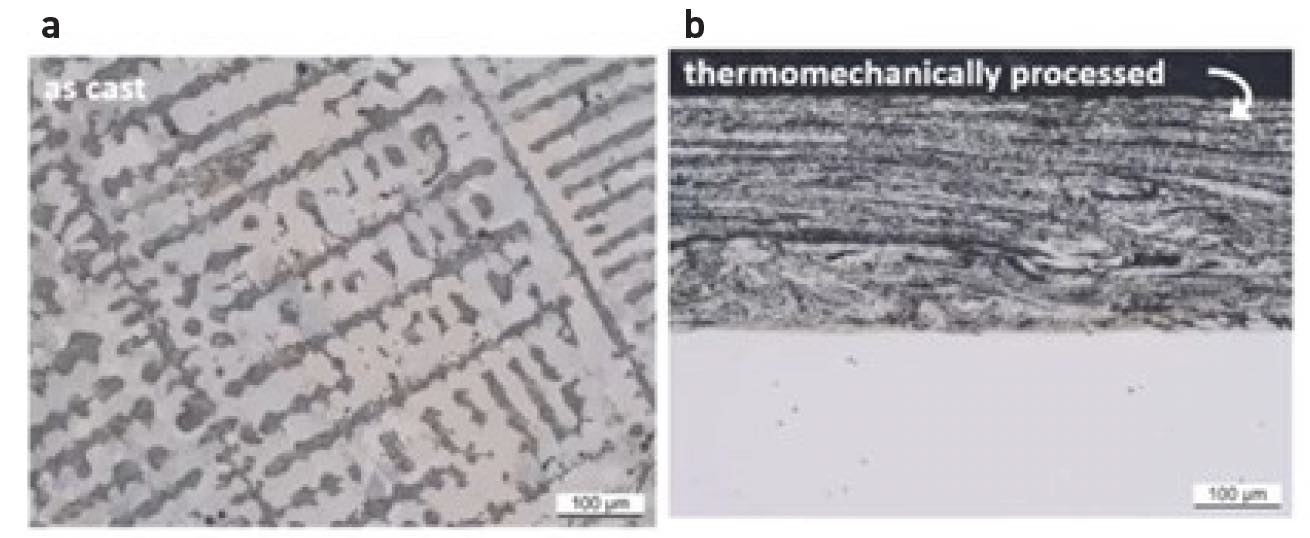 Figure 12. (a) Microstructure of Cr60Ni40 in cast state and (b) after friction surfacing, adjacent to the coating’s surface.
Thermomechanical processing by FS: CrNi alloy
Figure 12 shows thermomechanical processing by FS of Cr60Ni40 alloy. Microstructural investigations of the coating material were carried out and compared to the usual cast state. The wear behavior of the coatings, as well as the cast material, is examined under reciprocating sliding against 52100 ball-bearing steel by means of a ball-on-flat test rig, lubricated with silicone oil to prevent oxidation.
Changes induced by FS:
•
Reductions of domain size
•
Eutectic turns into supersaturated solid solution -> Ni austenite
•
Refinement of Ni-rich precipitates with Cr solid solution.
Cavitation tests were carried out using an ultrasonic vibratory test rig (ASTM G32) with cast specimens and friction-surfaced coatings. The coatings show less deformation and smaller disruptions, and wear rates in steady state were found to be higher for the cast and heat-treated samples than for the coatings due to a highly wear-resistant Cr-rich phase. Thus, in combination with a ductile substrate, these coatings are likely to extend the range of applicability of such high-temperature corrosion resistant alloys.
5
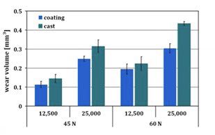 Figure 13. Wear volumes and average wear rates of the flats over normal force and number of cycles.4
The same material in the two states also was subjected to sliding wear tests. As seen in Figure 13 the wear volumes that were measured after the testing are slightly different (in blue, FS coatings, and in the green, the cast material). The FS coatings behave slightly better than the cast material state, having higher wear resistance. The wear is visible by grooves from abrasion and large delamination from surface fatigue
(see Figure 14).
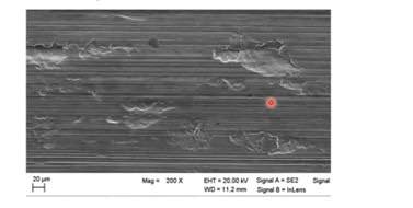 Figure 14. SEM figures of worn surface on cast Cr60Ni40: grooves and delamination.4
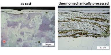 Figure 15. Cross sections of cast Cr60Ni40 after wear testing cut parallel to the sliding direction: (a) delaminated white etching layer (WEL) and (b) extensive white etching layers.4
Figure 15 shows worn surfaces for both samples. There is a protective nickel layer on the top, and the second bright layer is part of the surface of the sample, which is called the white etching layer (WEL).
4 They are hard and brittle, and the materials underneath have to support them
(see Figure 15).
In summary, some critical findings include the following:
Cavitation erosion
•
Multiphase materials–the weaker phase will be removed first; stronger phases stabilize the material
•
Refinement of phases and domain sizes: weaker phase regions are smaller in dimensions
•
Lower erosion rates through microstructure modifications
Sliding wear
•
Material removal by abrasion and surface fatigue in white etching layers for both states
•
Refinement of phases and domain sizes: multiple boundaries hinder plastic deformation below WEL
- Hard and brittle WEL are stabilized better and fracture less after thermomechanical processing
•
Lower wear rates through microstructure modification.
Summary
Different wear mechanisms contribute to material loss—dominated by chemistry, plastic deformation or fatigue. Knowing which mechanisms act may guide decisions on how to reduce the wear. At the same time, the interaction of phases, grains, etc., within the microstructure’s constituents plays a significant role in the wear progression. The microstructure of alloys can be adjusted, thus there is no need to use unique or more expensive alloys. FS discussed previously can be used to change the microstructure of alloys, and other methods to change microstructures also are available. There is still a need to understand the underlying mechanisms, the changes that are induced on the material and how these changes can affect or interact with the expected wear rates.
REFERENCES
1.
Zum Gahr, K. H. (1987),
Microstructure and wear of materials, 10, Elsevier.
2.
ASTM (2021), “Standard Test Method for Cavitation Erosion Using Vibratory Apparatus,” ASTM G32-16. Available at
www.astm.org/g0032-16r21e01.html.
3.
Schütte, M. R., Ehrich, J., Linsler, D. and Hanke, S. (2022), “Effects of microstructure modification by Friction Surfacing on wear behavior of Al alloys with different Si contents,”
Materials, 15 (5), p. 1641.
4.
Hanke, S., Fischer, A. and dos Santos, J. F. (2015), “Sliding wear behaviour of a Cr-base alloy after microstructure alterations induced by friction surfacing,”
Wear, 338, pp. 332-338.
5.
Hanke, S., Beyer, M., Silvonen, A., dos Santos, J. F. and Fischer, A. (2013), “Cavitation erosion of Cr60Ni40 coatings generated by friction surfacing,”
Wear, 301 (1-2), pp. 415-423.
Dr. Yulia Sosa is a freelance writer based in Peachtree City, Ga. You can contact her at dr.yulia.sosa@gmail.com.