Compressor fundamentals
By Dan Holdmeyer, Contributing Editor | TLT Lubrication Fundamentals January 2024
The type of compressor you should use depends on the requirements.

Compressors increase the pressure of a gas while reducing the volume the gas occupies. Think of the bicycle tire hand pump (see Figure 1). As the handle is raised, air is drawn into the cylinder. When the handle is pushed down, the air is pushed out through the hose and valve that can be connected to a bicycle tire, basketball, etc. If the tire, or ball, is flat, the air pushed into it causes it to take its full shape due to relatively low air pressure in the tire or ball. Once the tire or ball has taken its full shape, its volume is then quite constant, and the pump becomes a compressor. The tire pump is taking a volume of outside air, compressing it into the volume of the inflated tire or ball, raising the air pressure inside—thus, reducing the total volume of air and raising the pressure.
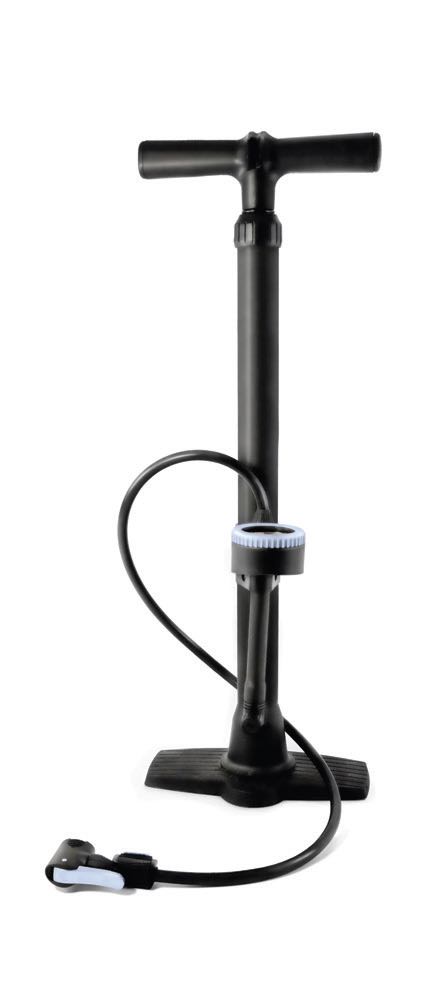
Figure 1. Bicycle tire hand pump.
Another familiar air compressor is the compressor that comes with most air mattresses. This compressor is a centrifugal compressor (see Figure 2), which consists of an impeller that rotates at high speed within a casing, drawing air in axially at the center of the impeller. The impeller blades accelerate the air, creating kinetic energy in the air, forcing it radially outward and in the direction of rotation into the casing, then out to the air mattress. This kinetic energy creates static pressure when the air is slowed in the larger portion of the casing and ultimately in the air mattress. The centrifugal compressor does not actually compress a large volume of air to a smaller volume and, thus, is limited on the pressure created.
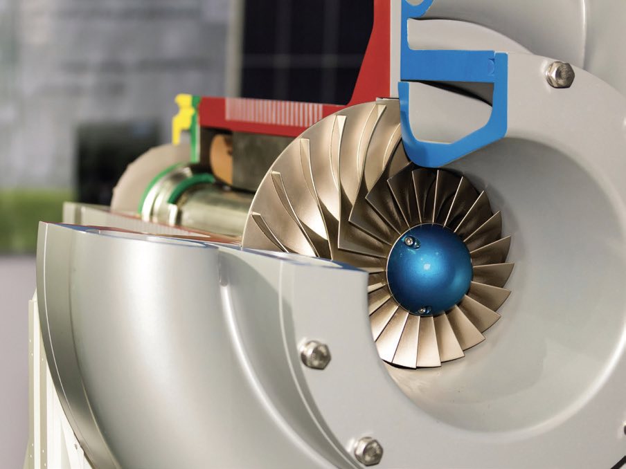
Figure 2. Centrifugal compressor.
A vacuum cleaner is another type of centrifugal compressor but working to create negative air displacement. The vacuum’s impeller rapidly draws outside air moving it toward the bag or dirt canister in the vacuum, creating slight pressure increase there, but more importantly drawing in dirt and debris with the swift air movement on the suction side of the vacuum cleaner.
An axial flow compressor (see Figure 3) generates air flow in line with its axis versus radially out from the impeller. Axial flow compressors consist of stationary blades attached to the casing and blades affixed to the rotating shaft. Kinetic energy is imparted to the air by the moving blades. As the air leaves the compressor, the air velocity is reduced and transformed into static head, or pressure. Axial flow compressors move large amounts of air. Besides, in various industrial applications, axial flow dynamic compressors are commonly used in aircraft engines to bring in more air into the turbine engine and increase its horsepower.
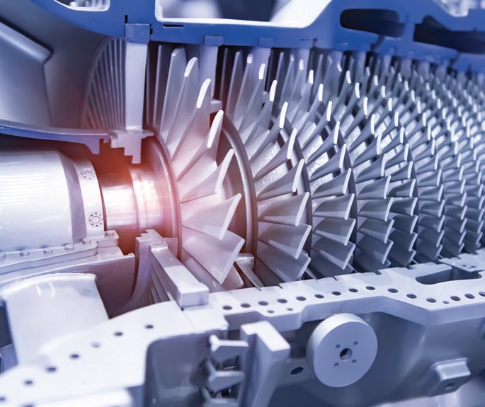
Figure 3. Axial flow compressor.
Centrifugal and axial flow compressors are categorized as dynamic compressors. They generate high speed air flow to generate air pressure. The compressors categorized as positive displacement compressors, however, take in a large volume of air, seal it from the outside, compress the large volume to a smaller volume and discharge it to a high-pressure receiver. A positive displacement compressor compresses the same volume of a gas (such as air) with each revolution of its shaft.
Most air compressors used in garages or shops operate on the same principle as the bicycle tire pump but with an electric motor driving the piston inside the cylinder to move the air. This is known as a reciprocating compressor and is capable of extremely high pressures. Primary reciprocating compressor components are pistons, rings, cylinders, valves, connecting rods and crankshafts, like what is found in internal combustion engines.
These compressors may be single-acting, or double-acting. Single-acting compressors compress the gas, like air, on only side of the piston, whereas double-acting compressors compress the gas on both sides of the piston (see Figure 4). The double-acting compressor requires additional components such as crosshead piston assembly with piston rod and packing between the crankshaft and double-acting compressing piston. Reciprocating compressors are used in a wide range of industrial applications.
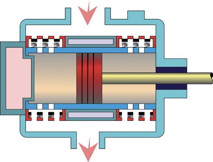
Figure 4. Double-acting reciprocating compressor.
Rotary screw compressors are another positive displacement compressor type. Rotary screw compressors can deliver large volumes of air efficiently producing more airflow per unit of horsepower versus other compressor designs. Rotary screw compressors eliminate the air pulsing typical of reciprocating compressors, thus eliminating the need for a surge tank after the compressor to dampen air pulsations. Most industrial applications have replaced their reciprocating compressors with rotary screw compressors because of the reliability and efficiency.
Most rotary screw compressors contain two mating screw shaped impellers. The gas (or air) is compressed by the action of these rotors. Some compressors rely on one rotor driving the other and some use timing gears on each rotor to drive them (see Figure 5).
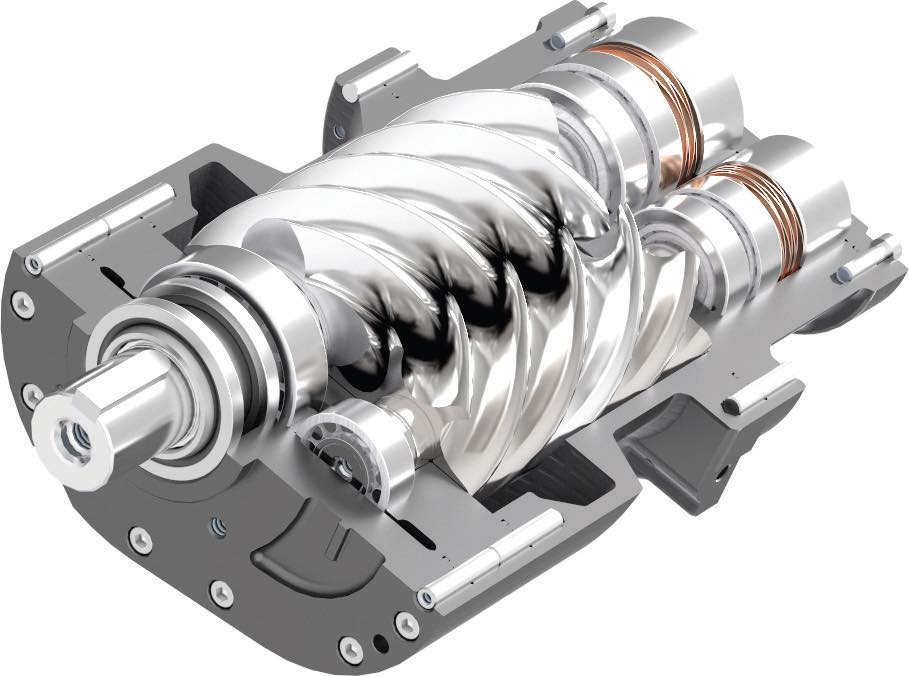
Figure 5. Rotary screw compressor. Figure courtesy of Airpol PPS, CC BY-SA 4.0, via Wikimedia Commons.
Rotary lobe compressors are considered positive displacement compressors even though the straight lobes in the compressor do not actually compress the gas within the compressor but just move the gas through the compressor. Compression occurs due to resistance on the discharge side of the compressor. For this reason, rotary lobe compressors are sometimes called blowers, or “Roots blowers” after an early popular brand of blower. Rotary lobe compressors are not as efficient as rotary screw compressors for gas compression, but lobe compressors also are capable of handling solids, slurries and a variety of liquids. Plastic molding companies often use rotary lobe compressors to transfer plastic pellets from storage and rail cars to molding machines in the plants. Rotary lobe compressors also are used in the food industry to transfer small fruits and vegetables such as cherries, peas and olives without damaging the product.
Lobe compressors are typically built with two or three lobed identical rotors that rotate in opposite directions inside a casing (see Figure 6). Timing gears drive each of the lobes to maintain their positions relative to each other. The lobes do not touch each other nor the casing.
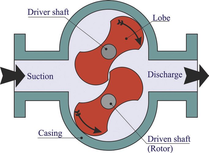
Figure 6. Rotary lobe compressor.
Scroll compressors are positive displacement compressors commonly used in refrigeration units and air conditioners. Scroll compressors do not need lubrication, which is a benefit in not potentially contaminating the refrigerant in air conditioning or refrigeration units, and lower maintenance costs in not requiring oil changes. The rotating scroll does not contact the stationary scroll, thus making it a very quiet compressor and cooler operation (see Figure 7).
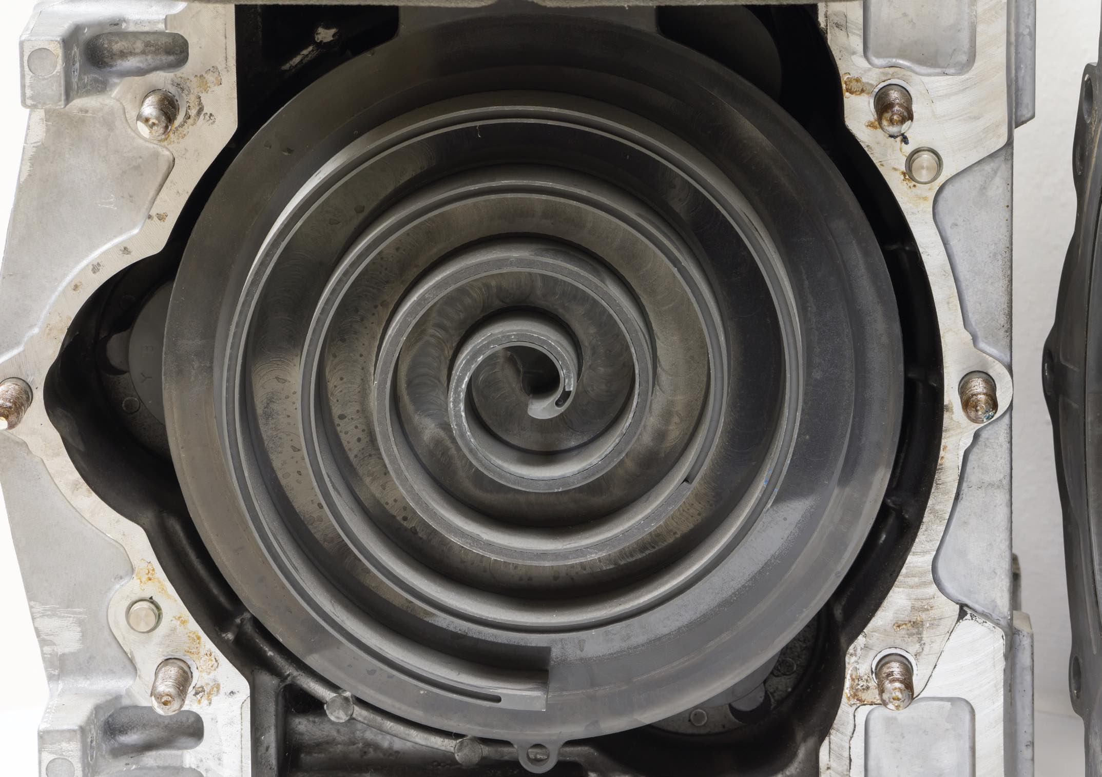
Figure 7. Scroll compressor.
Scroll compressors have fewer moving parts making breakdowns less likely, lasting approximately 10-15 years if the refrigerant is maintained and not contaminated. Repairing a scroll compressor is difficult and is usually simply replaced with a new one. Due to the precise machining required to manufacture the scrolls, these compressors are expensive and don’t lend themselves well for larger scale compressors. Large refrigeration systems use other compressor types.
So, which compressor is best? That depends on the requirements. Reciprocating compressors are preferred for high-pressure applications. Dynamic, centrifugal and axial flow compressors deliver high volumes of compressed air most effectively. Rotary screw compressors are common for applications in between.
Reciprocating, centrifugal and axial flow compressors also may be configured as multi-stage compressors. Multi-stage compressors generate higher pressures than their single-stage counterparts. As one might imagine, in a multi-stage compressor the second stage of the compressor takes in the higher-pressure discharge air from the first stage and compresses it to even higher pressure. The third stage takes the second stage discharge and compresses it to even higher pressure and so on.
Cooling of the compressed gas between the stages is required for a few reasons, such as efficiency improvements, protection of compressor components and reduced potential of fire or even explosion. When a gas is compressed and pressurized, the temperature also increases potentially to the point of igniting any lubricant or deposits in the compressor. Additionally, by cooling the discharge air, it condenses the volume, enabling the next stage to compress more gas to the next pressure level.
Now we are getting into some considerations beyond just bearing and ring wear protection needed in lubricating these compressors. We will discuss these considerations next month since we now have a fundamental understanding of common compressors in use today.
Dan Holdmeyer is retired from Chevron Lubricants and is based in Washington, Mo. You can reach him at dan.holdmeyer@gmail.com.