Gears
By Dan Holdmeyer, Contributing Editor | TLT Lubrication Fundamentals November 2023
These common gearset designs all have unique characteristics and are used in various applications.
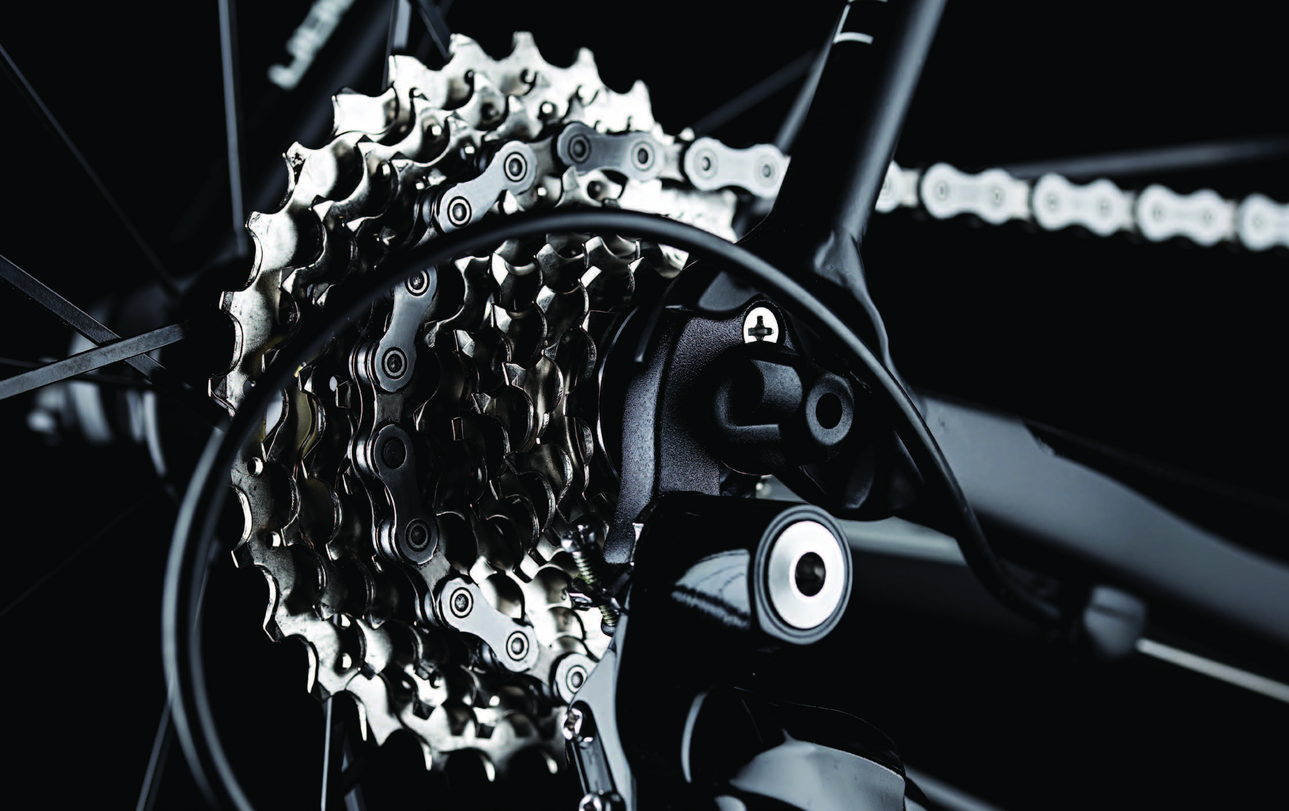
Two reasons for gears are to increase output torque or to increase the output speed. The sprockets and chain of a multi-speed bicycle are good familiar visuals that demonstrate the relationship between torque and speed.
In low “gear,” the chain is meshed with the cogs, or teeth, of the smallest sprocket of the set of sprockets attached to the pedals and also is meshed with the cogs of the largest sprocket of the set attached to the rear, or driven, wheel. Low gear is used to start moving the bicycle or to continue moving up a steep incline. Low gear enables the rider’s weight on the pedal to provide enough torque to the driven wheel to move the bicycle forward. In low gear the pedals must make several revolutions for each revolution of the driven wheel. Thus, low gear provides high torque but low speed.
In high “gear,” the chain is meshed with the cogs of the largest sprocket attached to the pedals and meshed with the smallest sprocket attached to the driven wheel. This configuration is ideal for reaching maximum speed with the minimal number of pedal revolutions on level to downhill terrain, and relatively small inclines. It converts pedal force to high speed at the driven wheel, but with low torque. Eventually, with enough incline to climb, the bicyclist’s total weight on the pedal cannot generate enough torque to the driven wheel to move the bicycle. Thus, to maximize torque, speed is sacrificed, and to get maximum speed, torque is limited.
We say bicycle “gear” because it relates nicely to the gear ratios of the automobile transmission. Sprockets on the bicycle are not gears. The cogs of the sprockets are designed to mesh with, and transmit power via, the chain. Gears also have cogs, or more commonly called “teeth,” that interact directly with the teeth of another gear. Gear teeth have distinct configurations and profiles to efficiently mesh with each other for various purposes and advantages.
When we envision a simple gearset, we likely think of something like the gearset in Figure 1. The gear teeth are much wider than the typical cog of a sprocket, enabling them to transmit more power. Also, notice the straight teeth are aligned with the shafts of the gears, making this a spur gearset. (The teeth would be parallel to the shaft if a shaft were shown in Figure 1.) Spur gearsets are relatively simple and inexpensive to manufacture. It is difficult to see in Figure 1, but only one tooth per gear is fully engaged and transmitting power, which makes them noisier than other gear tooth configurations.

Figure 1. Spur gearset.
The spur gear is the easiest tooth configuration to discuss the engagement of the teeth as shown in Figure 2. The lower gear is the driving gear, and the rotation is clockwise. The driven gear (the upper gear in Figure 2) is then rotated counterclockwise. Notice the face of each tooth has a curved profile that increases efficiency in the gearset because it momentarily eliminates sliding friction between the engaged teeth when contact is at the gear pitch circles. The pitch circles in Figure 2 are indicated by the red lines that meet at point C. The blue line shows the line of contact between the gears with the beginning of the next set of gear teeth engagement at point A. The driving gear’s tooth slides into the driven gear tooth until it reaches the pitch circles at point C where the sliding action stops. After the line of contact point C, the driving gear tooth begins to slide out of the driven gear until it is no longer in contact at point E. (You’ll have to imagine the rotation of the gears in Figure 2.) At the line of contact point C, there is no sliding friction, just the rolling of the teeth’s curved profiles over each other—still some friction but not nearly as much as the sliding friction.
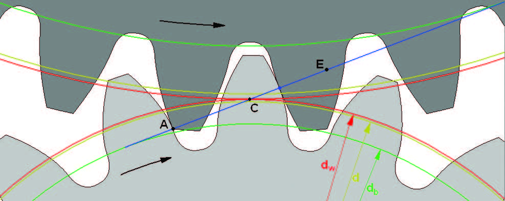
Figure 2. Involute gear engagement. Figure courtesy of Bokai, Public domain, via Wikimedia Commons.
Interestingly, the sliding action of the driving gear tooth into the pitch circle and then out of the driven gear tooth leads to plastic deformation of the teeth surfaces. Over time it is not uncommon to see a ridge at the pitch circle of the driven tooth and a groove at the pitch circle of the driving gear tooth due to the plastic deformation of the metal surfaces.
Gear spacing also is critical in gear design. The gear teeth tips do not reach the root of the opposing gear allowing for any contamination and to not force the gears away from each other. This gap is called Figure 1. Spur gearset. Figure 2. Involute gear engagement. Figure courtesy of Bokai, Public domain, via Wikimedia Commons. Figure 3. Rack and pinion. “clearance.” The gap between the back side of the driving gear tooth and the next driven gear tooth is called “backlash.” Backlash becomes critical when gearsets operate in forward and reverse directions. The loud banging of gears when the direction of gear rotation is reversed indicates too much backlash.
The rack and pinion gear configuration (see Figure 3) is another form of spur gears but on a straight rack engaged with a pinion gear. The rack or the pinion can either be the driving or driven gear.
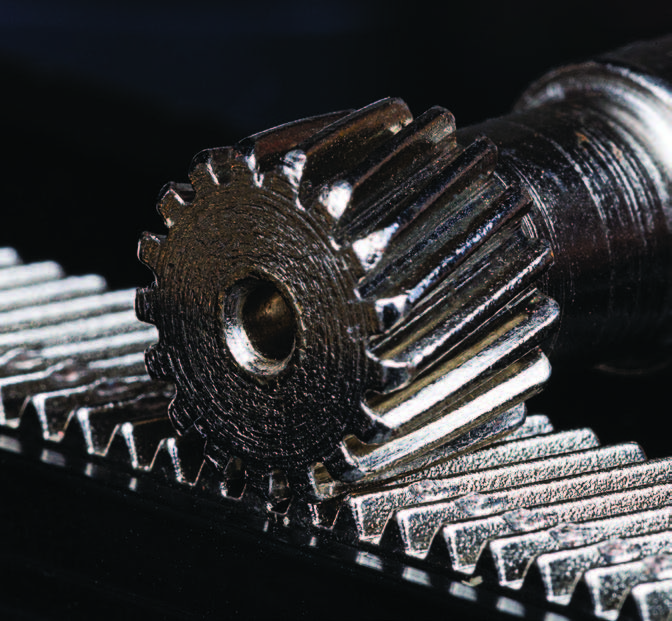
Figure 3. Rack and pinion.
The helical gear configuration provides higher load carrying capacity than spur gears (see Figure 4). The helical gear teeth are not parallel to the shaft, which continually engages multiple teeth, thus the higher load capacity. This configuration generates smoother power transmission with less noise than spur gears. Helical gears are typically used in parallel axis gearing such as automotive transmissions and large industrial gearboxes. Because the helical gear teeth are at an angle to the axle, or gear shaft, they do generate axial thrust putting added stress on gear shaft bearings. Heavily loaded helical gearsets may require the use of thrust bearings in the gearbox to counter the axial load.
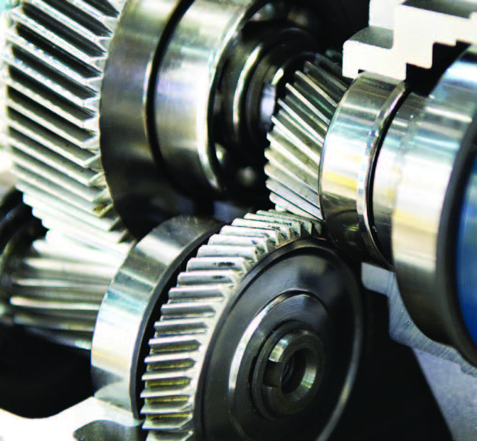
Figure 4. Helical gears.
Double helical, or herringbone, gears alleviate the need for thrust bearings needed in helical gearsets (see Figure 5). They are typically used in large, heavily loaded, parallel axis gearboxes. They are not used in automotive manual transmissions as herringbone gears cannot slide into and out of engagement. Additionally, they are more expensive to manufacture.
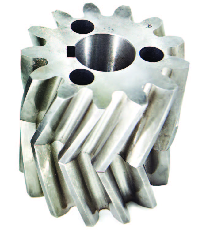
Figure 5. Herringbone or double helical gears.
A third reason for gears is to change direction of mechanical rotation. Bevel gears are mounted on shafts that typically intersect at 90 degrees to each other. If a cone were place on each gear that lined up with the slope of each gear’s teeth tips, the cone tips would intersect directly above the lower gear shaft and straight out from the horizontal gear shaft in Figure 6. Depending on which gear in Figure 6 is the driving gear, the output speed is either increased or decreased, and the torque decreased or increased, respectively. If both gears were of equal size, the output speed and torque would not change; however, the direction of rotation would change, and the gears might be called miter gears.
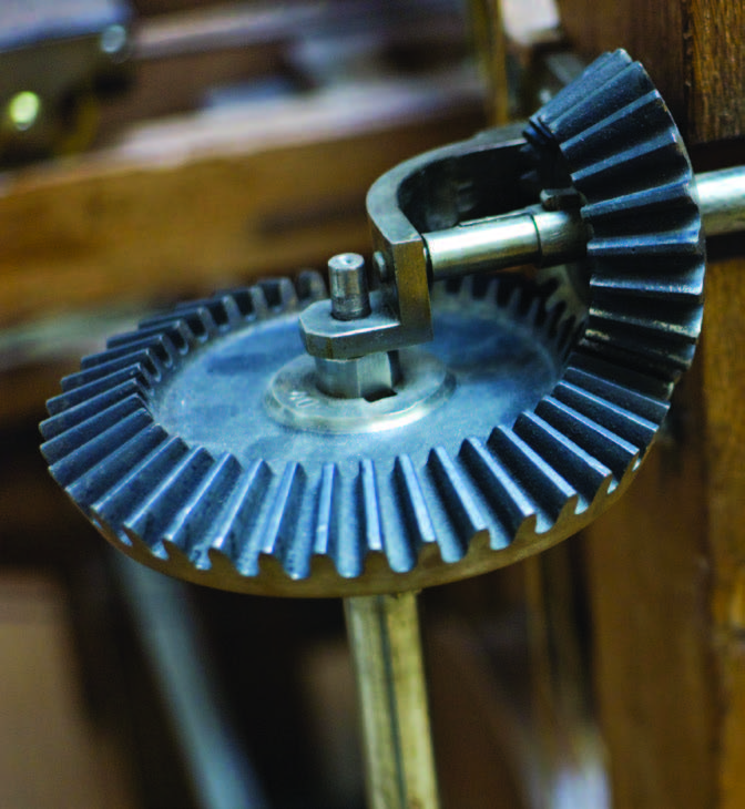
Figure 6. Bevel gears. Figure courtesy of Alexandre Vialle, CC BY 2.0, via Wikimedia Commons.
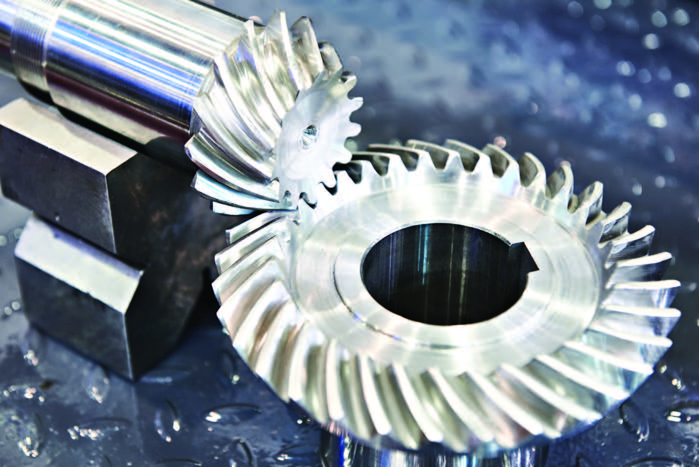
Figure 7. Spiral bevel gears.
Spiral bevel gears take the helical gear concept of parallel shaft gearsets to bevel gearsets. Spiral bevel gears run quieter and carry heavier loads than straight cut bevel gears. Notice in Figure 7 the gear teeth are no longer straight. They need to curve, or spiral, to engage with the opposing gear. All the other parameters of bevel gears apply to spiral bevel gears.
Hypoid gears are spiral bevel gears with the unique characteristic of the input and output shafts do not intersect (see Figure 8). The most common application of this gear configuration is the rear axle differential in rear-wheel-drive vehicles. Like spiral bevel gears, the hypoid gear converts the drive shaft mechanical rotation 90 degrees to the wheel axle’s mechanical rotation. The input shaft pinion is offset, lowered, from the axle shaft to help lower the drive shaft from the car transmission to the axle, to lower the “hump” in floor of the car passenger cabin. The hypoid gear design further improves the load capacity over the spiral bevel gear but also increases the amount of sliding friction between the gear teeth. These design characteristics mandate additional lubrication properties that we’ll discuss next month.
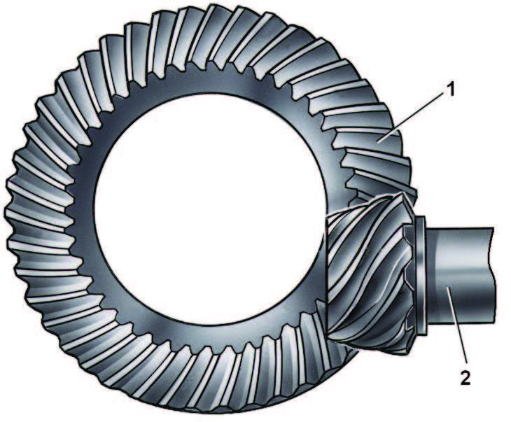
Figure 8. Hypoid gears. Figure courtesy of Sam novo, Public domain, via Wikimedia Commons.
A worm gearset pictured in Figure 9 also changes the direction of mechanical rotation but typically at a much higher gear ratio, typically between 30:1 and 50:1. The larger “ring” gear is always on the output shaft. The input shaft is connected to the “worm” gear, sometimes called the “screw” drive because the continuous gear tooth, or teeth, look like a screw. The meshing of the ring gear and worm gear teeth results in extreme sliding friction between the teeth. For that reason, the gears are made from dissimilar metals to avoid friction welding of the gears. All the previously mentioned gear configurations used similar metals in mesh. The worm gear makes multiple revolutions for each ring gear rotation and is made of hardened steel. The ring gear is commonly made of bronze to prevent welding but also to conform to the worm gear. It is not unusual to have high levels of copper alloy wear metals show up in worm gear oil analysis as the ring gear “breaks-in.” Some will say the worm gear cannot be reversed, but it can be reversed only by reversing the input shaft rotation. The worm gearset cannot be driven in either direction by the output shaft.
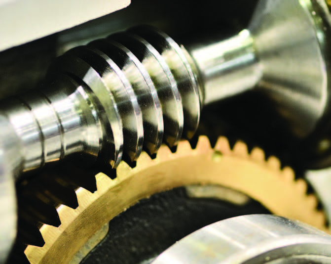
Figure 9. Worm gearset.
The planetary gearset is a unique gear configuration as seen in Figure 10. The gear in the center is called the sun gear. The three gears meshed with the sun gear are called the planetary gears, or sometimes called the “star” or “planet” gears. Missing in Figure 10 is the planet carrier that maintains the planetary gears’ position relative to each other. Finally, the outermost gear with inner teeth is called the ring gear, or sometimes the annulus. The gear teeth can be spur or helical. Planetary gearsets are most often used in automotive automatic and dual clutch transmissions, as well as in final drives of heavy off-road equipment.
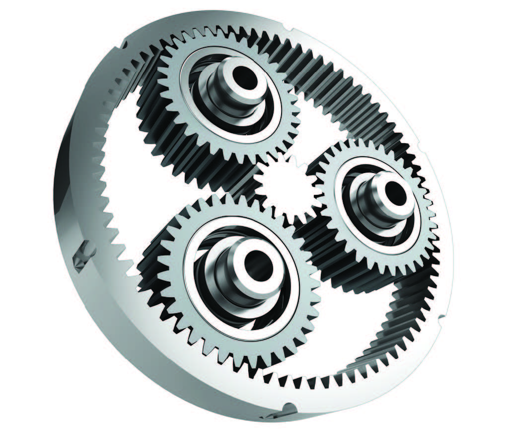
Figure 10. Planetary gearset.
Those are some of the most common gearset designs. Next month we will discuss lubrication of these various gearsets in various applications.

Dan Holdmeyer is retired from Chevron Lubricants and is based in Washington, Mo. You can reach him at dan.holdmeyer@gmail.com.