Hydraulics: Accumulators and filters
By Dan Holdmeyer, Contributing Editor | TLT Lubrication Fundamentals August 2023
Hydraulic fluid energy can be stored in accumulators, while filters protect from contamination.
A hydraulic system works by converting mechanical energy from a motor or engine to hydraulic fluid flow via the hydraulic pump. Hydraulic fluid pressure is generated when the fluid flow is resisted by the work to be done by an actuator, such as a cylinder lifting an elevator or car. Thus, the hydraulic fluid energy is converted back to mechanical energy when the cylinder moves a load or when a hydraulic motor applies torque to a shaft that may drive a vehicle. This all requires hydraulic fluid flow. But can hydraulic fluid energy be stored?
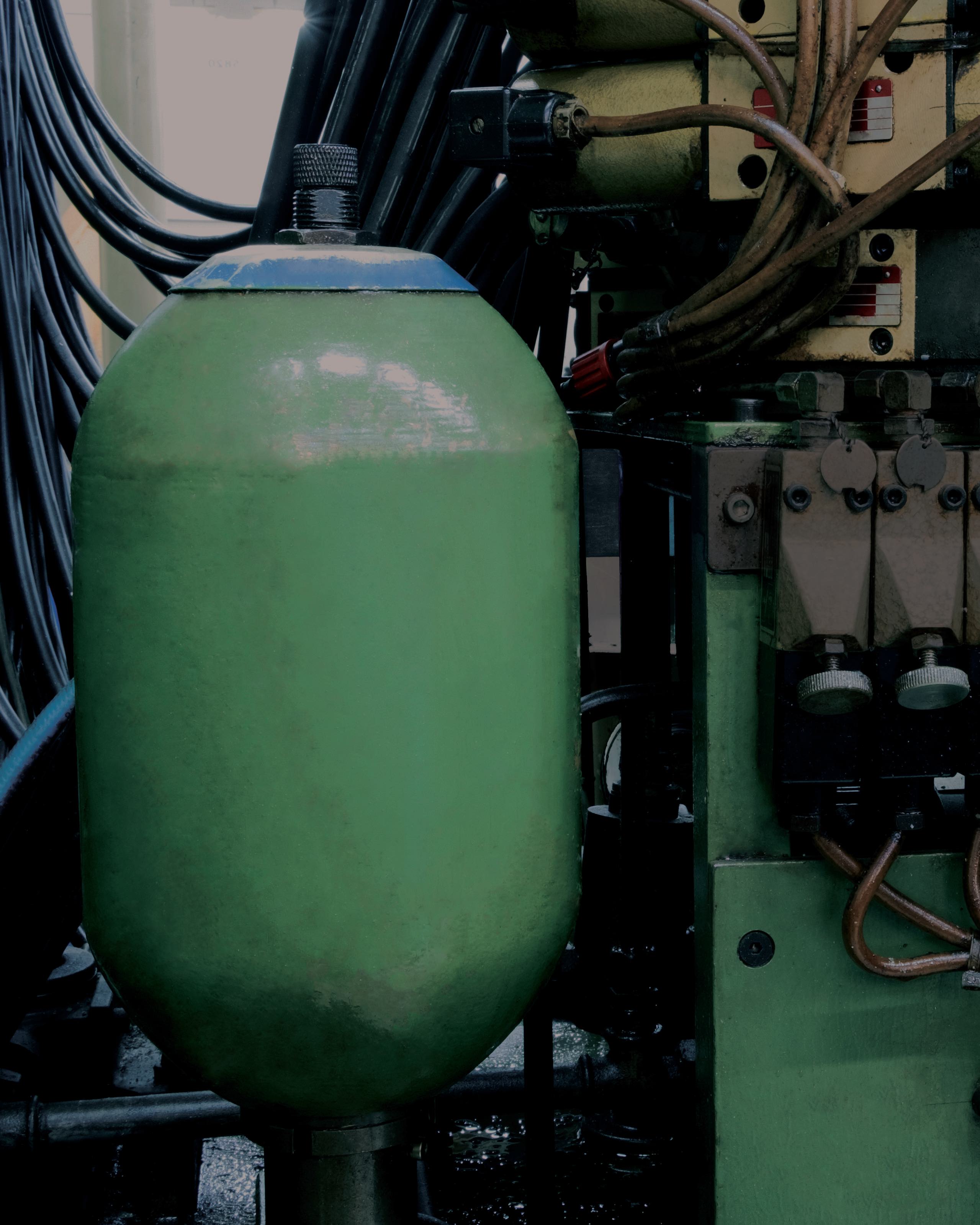
Yes. Hydraulic accumulators can store hydraulic fluid energy and release it as needed in the hydraulic system but only for a relatively short period of time (see Figure 1).
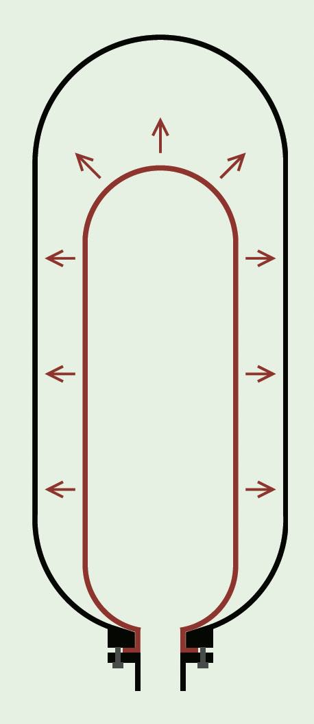
Figure 1. Typical hydraulic accumulator. Figure courtesy of MasterTriangle12, CC BY-SA 4.0, via Wikimedia Commons.
The energy stored under pressure in an accumulator can be used when a short-term large volume of hydraulic fluid energy is needed. For example, a hydraulically operated clamp may need to close quickly via a cylinder, but once the clamp is closed, minimal fluid flow is required to overcome internal leakage and to maintain clamping pressure. Thus, the hydraulic pump can recharge the accumulator while the clamp is closed and system fluid flow demand is low, versus designing the system with a higher volume pump to generate the flow needed to quickly close the clamp.
Accumulators also can be used to maintain pressure while the system is not running. The accumulator maintains system pressure by replacing fluid volume that is lost due to internal leakage. Eventually the accumulator fluid volume will need to be replenished. The accumulator cannot maintain system pressure indefinitely.
Accumulators also help smooth out system pulsations sometimes generated by multi-piston pumps, engine driven systems or with a sudden change in the direction of the hydraulic fluid’s flow. Repeated hydraulic shocks, such as these, can burst system components, particularly hoses and piping. The accumulators act as a “shock absorber” for the system.
Multiple accumulators may be used in a single hydraulic system, but not all hydraulic systems have accumulators. The purpose for the accumulator may dictate what type, and location, of accumulator(s) is (are) used by the system designer. Or the design engineer may be able to make compromises to the number of accumulators due to costs and effects of the accumulators. Accumulators installed to dampen pump pulsations will be placed closer to the pump, whereas accumulators used to quickly extend a large cylinder will likely be placed near the cylinder to minimize response time delay or energy lost to piping flow resistance. The accumulator discharge provides greater energy for the short duration to empty the accumulator than can be generated by the system pump.
Compressed gas, sometimes referred to as “hydro-pneumatic,” accumulators are the most popular ones used. Hydropneumatic accumulators will have an internal bladder, diaphragm or piston to keep the compressed gas separated from the hydraulic fluid. Typically, an inert gas such as nitrogen is used because the oxygen in Earth’s air under pressure with oil can be an explosive mixture. Highpressure systems usually require the gas in the empty system accumulator to be near the operating pressure. A plate at the bottom of the accumulator is designed to prevent the bladder from extruding out with the high internal pressure when the hydraulic system pressure is low. Pressure regulating valves also may be required on the accumulator discharge to prevent damage to the rest of the hydraulic system.
Per Pascal’s principle, as the compressed gas accumulator releases its stored energy, the volume of internal gas increases and, thus, the hydraulic fluid pressure from the accumulator decreases. (Refer to the May 2023 TLT Lubrication Fundamentals article titled “Fundamentals of hydraulics: Pascal’s principle and pump designs.”)
Spring loaded accumulators are commonly used in simpler hydraulic systems. Spring type accumulators operate similarly except instead of compressed gas, a coiled spring exerts the pressure. As with the gas accumulator, the spring accumulator discharge pressure decreases proportionally to the spring’s extension.
Well-designed accumulators should last years without incident.
Hydraulic system filters on the other hand require much more attention and change outs than do accumulators (see Figure 2). Almost every hydraulic system contains more than one filter. Hydraulic filters are placed at specific locations in the system to remove, or block, contaminants at different points. The most common filters found in hydraulic systems are low-, medium- and high-pressure filters, magnetic in-tank filters, pump inlet and fill strainers and tank breathers.
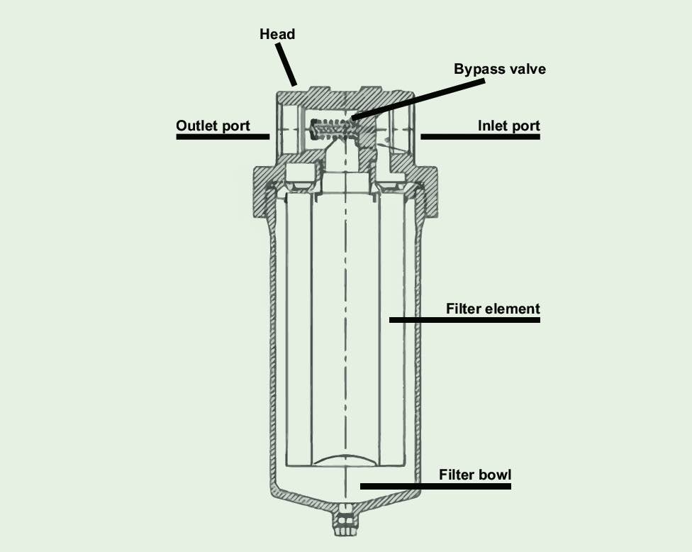
Figure 2. Typical hydraulic filter construction.
In the June 2023 TLT Lubrication Fundamentals article titled “Fundamentals of hydraulics: Reservoir designed to do more than hold the fluid,” we discussed in some detail magnetic filters in the reservoir and reservoir breathers, both particulate and desiccant types.
The breathers have particulate filters to reduce the amount of dust and dirt that enters the system when the reservoir breathes due to changes in the amount of oil in the reservoir. In humid environments, breathers are often fitted with a desiccant breather that removes both particulate and moisture from the air as the reservoir breathes. It is much easier to keep dirt and moisture out of the hydraulic fluid than it is to remove these contaminants.
The magnetic filter, which is just a magnet submerged in the fluid, collects ferrous wear debris to minimize additional component wear. The collected wear debris is usually quite fine and indicative of normal wear. Large metal pieces collected on the magnet indicate more catastrophic wear and potential failure. Some magnet filters are attached to the drain plug and can only be checked when changing the fluid. Other magnetic filters are suspended in the oil via a rod that can be removed and checked for wear debris on a regular schedule.
Pump inlet strainers protect the pump from relatively large contaminants that may have entered the reservoir. If a reservoir were kept sealed against outside contamination, the pump inlet strainer would not be necessary. Unfortunately, many reservoirs are left with missing fill caps or worn pipe grommets that allow particulate contamination, some as large as nuts and bolts. Pump inlet strainers should not be finer than a 200-mesh screen, which has openings about 74 microns in size. Too fine a mesh screen could restrict pump inlet flow enough to cause pump cavitation. (Refer to the February 2022 TLT Lubrication Fundamentals article titled “Air entrainment, aeration, cavitation and foaming: How are they related?”)
Fill point strainers are another type of filter to keep out contamination. Every time the hydraulic system is opened, contamination is a potential hazard to the system. These strainers should not be removed even if it slows the fluid refilling process. Quick connections should be installed to allow faster, clean refilling if needed.
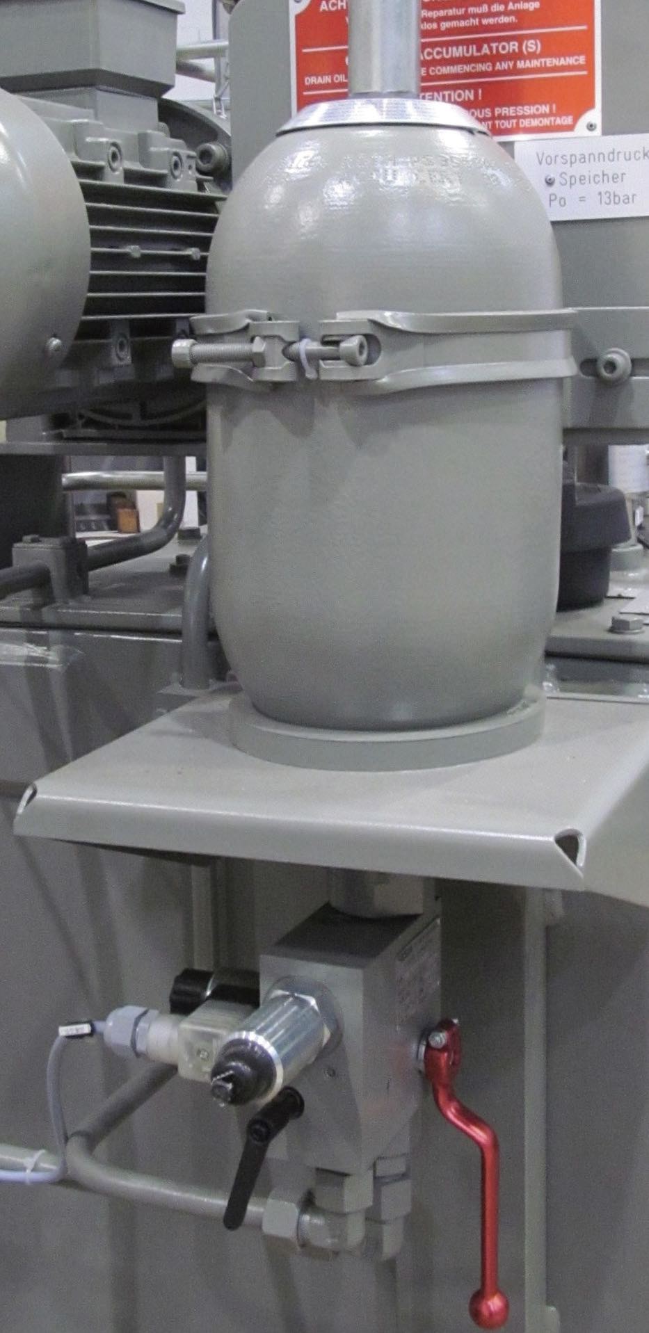
Photo courtesy of Andy king50, CC BY-SA 3.0, via Wikimedia Commons.
The high-, medium- and low-pressure filters remove contaminants from the fluid flowing through the system to protect the components from abrasive wear via particulate contamination. These are often referred to as “full-flow filters.” The hydraulic filters between pump and downstream valves and actuators are referred to as high, or medium, pressure filters, and the hydraulic filters on the oil lines returning to the reservoir are low pressure or return line filters. Some systems may only have return line filters relying on the fluid in the reservoir to not get contaminated there and, thus, the fluid is maintained “clean” before it starts to circulate through the system. The return line filter would catch any wear debris or other contamination generated or picked up by the fluid during circulation through the system.
Most full-flow filters should be changed every six months to one year. However, some systems operate in dirtier environments and may require more frequent filter changes. Pressure differential gauges on the filter will indicate when a filter has reached its maximum life. These filters should be changed before the filter goes into “bypass” mode, and the oil no longer gets filtered, or worse, if the filter does not have a bypass valve, the filter could rupture and then the filtered debris stored in the filter would dump into the system.
More complicated systems may incorporate hydraulic pilot circuits that operate at high pressure and have sensitive control valves. These systems often require a higher cleanliness level to protect the valves. Additional high-pressure filters are placed just upstream from the valves.
To help clean the hydraulic fluid even more, offline, or “kidney-loop,” filtration may be added to the system. A smaller amount of oil relative to the full-flow filters mentioned previously is continuously pulled from the system and filtered, usually with a finer filter. Finer filtration can be achieved more easily without the volume of fluid flow seen by the full-flow filters.
Some hydraulic system filters look like spin-on engine filters, but they are not the same. Engine oil filters typically do not clean the oil enough for a hydraulic system. Filter ratings and specifications are a much larger topic that will need to be addressed in another article.
Dan Holdmeyer is retired from Chevron Lubricants and is based in Washington, Mo. You can reach him at dan.holdmeyer@gmail.com.