Fundamentals of hydraulics: Actuators and valves—the muscles and brains of the hydraulic system
By Dan Holdmeyer, Contributing Editor | TLT Lubrication Fundamentals July 2023
Valves guide and control the work of the hydraulic system while actuators perform the work.
Hydraulic actuators and motors are the components of the hydraulic system that do the work the hydraulic system was designed to perform.
Last month we discussed the myriad of functions the hydraulic reservoir performs besides holding the hydraulic fluid for the pump to circulate. Now let’s look at how that fluid flow is used and controlled.
Hydraulic actuators and motors are the components of the hydraulic system that do the work the hydraulic system was designed to perform. Hydraulic actuators convert hydraulic fluid flow into mechanical operation of linear, rotary or oscillatory motion. External resistance to mechanical operation, and, thus, resistance to internal fluid flow, creates the pressure within the hydraulic system.
Generally there are two types of actuators: linear and rotary. Three common mechanical motions created via these actuators are linear, continuous rotation or oscillatory rotation from a few degrees up to 360 degrees. There is a myriad of design variations of these actuators. Let’s review a few of the more common designs.
Linear actuators are more commonly called hydraulic cylinders. Components of the hydraulic cylinder are the cylinder, within which is a piston connected to a rod(s) that extends beyond the cylinder to connect to the object being moved. Inlet and outlet ports allow the flow of the hydraulic fluid in and out of each end of the cylinder. Seals keep the fluid inside the cylinder and hoses but also seal the piston within the cylinder to enable pressure to build within the cylinder to force the piston and the rod against a load.
Some hydraulic cylinders only have one inlet/outlet port at the base cap, or end cap, which is opposite the cylinder end with the external rod, known as the rod end of the cylinder. These cylinders are called single acting cylinders. Lifts, or elevators, use single acting cylinders that rely on gravity or the mass of the elevator to push the rod back into the cylinder. A spring load may be used when gravity will not retract the piston inside the cylinder.
Double acting hydraulic cylinders have inlet/outlet ports on each end of the cylinder. The hydraulic fluid flow drives the piston in both directions, doing work in both directions. As an example, double acting cylinders are common on excavators, backhoes and mobile equipment to extend and flex the boom or to actuate scooping or dumping the bucket.
Double rod hydraulic cylinders are less common but are not to be confused with double acting cylinders. Many double rod cylinders have external rods extending from each end of the cylinder, so a single cylinder actuates equally against two loads. Other double rod cylinders have two external rods on one end of the cylinder, but these are mostly used in pneumatic, not hydraulic, systems. Double rod cylinders do not have to be double acting, although most double rod cylinders do have two inlet/outlet ports and are also, thus, double acting (see Figure 1).
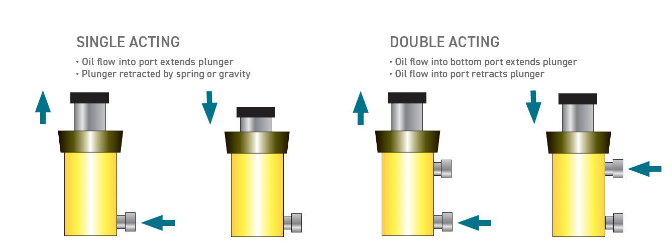
Figure 1. Single acting versus double acting cylinders.
Rotary actuators convert hydraulic fluid, or air, pressure to torque and create a rotary or oscillating motion. Hydraulic fluids are nearly incompressible enabling more precise control and greater torque in compact design relative to air, or pneumatic systems. Oscillating motors are rotary actuators often used in opening and closing large remote valves, or in pick-and-place robotic operations, to name a few likely applications. These rotary actuators typically are used in applications requiring up to 360 degrees of rotation. Rack-and-pinion, scotch yoke and vane rotary actuators are the most common designs used with hydraulic fluids.
In a rack-and-pinion activator, a piston is extended or retracted via fluid pressure to move a rack (a bar with gear teeth) past a gear connected to the output shaft, allowing precise control of the direction and degree of rotation of the shaft. Similarly, a scotch yoke assembly can be driven by a piston to create rotation of the output shaft. The scotch yoke actuator is limited to about 90 degrees of rotation but can create higher torque than a rack-and-pinion actuator of the same size. The rack-and-pinion actuator will provide consistent torque throughout the cycle and is limited in degrees of rotation only by the length of the rack, but usually not more than 360 degrees.
Vane rotary activators are connected directly to the output shaft. Vane rotary actuators are a couple of vanes attached to a rotor within a chamber where hydraulic fluid flows into either side of the vanes to rotate the rotor. The rotor is connected to the output shaft (see Figure 2).
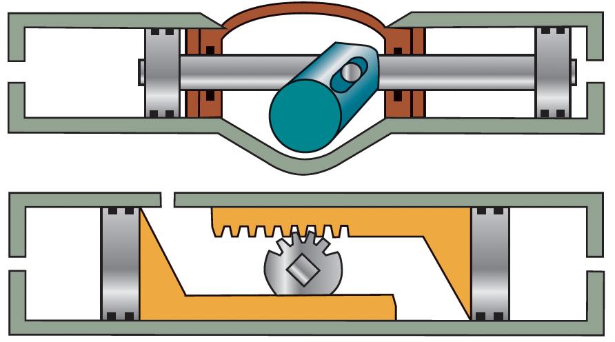
Figure 2. Scotch yoke and rack-and-pinion actuators.
Hydraulic motors are another hydraulic rotary actuator type. They are used when rotation beyond one full rotation, or continuous rotation, is required. Hydraulic motors are very similar in design to hydraulic pumps. In fact, many hydraulic pumps can be used as motors. The main difference is the pump converts mechanical energy from a motor or engine to hydraulic fluid energy, and the motor converts that hydraulic fluid energy back into rotational mechanical energy. Additionally, hydraulic motors are not going to have variable volume capabilities as do some hydraulic pumps.
Hydraulic motors generally have the same categories as do pumps. Motor types include gear, vane and piston. Piston motors are more expensive but provide the greatest efficiency and can generate high torque at low speeds. Vane motors are quieter and less expensive. Gear motors also are less expensive and are more tolerant of fluid contamination.
It may seem counterintuitive to convert mechanical energy into hydraulic fluid energy only to convert it back to mechanical energy, but there are several benefits to hydraulic systems. They have high power density, are easily reversible and have continuously variable speed. Power density is basically the amount of power transferred divided by the unit volume. Think about the gearing, linkage, shafts and drives it would take to articulate a backhoe bucket without hydraulics. Hydraulics deliver a great deal of power with relatively little equipment and with precision. The backlash inherited in gears and linkage is eliminated with hydraulics, which improves precision of movement.
Hydraulic valves control the fluid flow within the hydraulic system, which, in turn, controls the speed, and direction, of motion. Some systems may require just a couple of valves, while others utilize multiple valves to optimize performance in more complex systems. There are many different hydraulic valves designs available that generally control three fluid characteristics: pressure, direction and flow (volume).
Pressure control valves, as the name implies, manage the fluid pressure in the hydraulic system. Depending on the position within the system, the pressure control valves are required to perform different functions and, thus, have different names. Some pressure control valve names are relief, reducing, counterbalance and sequencing valves.
Pressure relief valves are used to control the pressure going into the hydraulic system when placed immediately downstream from the hydraulic pump. The relief valve is generally set at 100 to 150 psi above the maximum required pressure for the system to perform but below the pressure limit of any system components to not burst or break any of the components. The relief valve opens at the set pressure and returns the hydraulic fluid back to the reservoir without going through the system. Pressure reducing valves work similarly but are placed strategically in certain sections of the system that may have lower pressure limits.
A check valve is a directional flow valve that allows free flow of fluid in one direction and prevents any flow in the reverse direction. Check valves may be used individually but are also critical components within other valve types, as are relief valves.
Counterbalancing valves allow free flow of fluid through an internal check valve preventing reverse flow through the valve until a pre-set pressure limit is reached when a relief valve in the counterbalance valve opens to allow reverse flow. Counterbalancing valves are used in applications such as a hydraulic cylinder to set the maximum load limit and to control the rate of cylinder actuation.
Sequencing valves, true to name, control the sequencing of multiple actuators in a system. The hydraulic fluid flows to the first actuator until it reaches its design limit, and the pressure rises to open a valve port to the next actuator.
Directional control valves allow, stop and change the direction of fluid flow. Directional valves usually consist of a spool mechanically or electrically rotated or slid to align with open ports in a housing. These ports are labeled to indicate to where the port is open. A and B are open to the actuator, P is open to the pump, and T is open to the tank, or reservoir.
The simplest of these valves are two-way (2/2) valves that have two spool positions and two ports. A relief valve is a 2/2 valve. A more common directional valve is a four-way (4/3) valve, which has four ports (A, B, P and T, as noted previously) and three positions, commonly extend, retract and neutral.
The neutral position is generally the center position as in Figure 1. The center position also has a few options, and the hydraulic system may be identified by the center position option. An open center connects all four ports. A closed center valve blocks all four ports. A closed center, center position will lock a cylinder in its position not allowing the load to drop (see Figure 3).
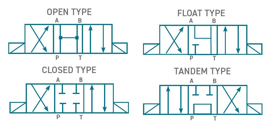
Figure 3. Typical four-way directional control valve.
Directional valves can be controlled manually typically with a lever or potentially with a steering wheel, mechanically as with a stop that moves the spool within the valve, electronically with a solenoid or by an internal hydraulic port to the valve to move the spool when a specified pressure is reached.
Hydraulic flow control valves regulate flow rate within the hydraulic system to ensure optimum performance. Regulating the flow rate of the fluid directly regulates the speed of motors and cylinders.
Flow control valves general designs are categorized by their internal aperture closing structure: gate, needle, diaphragm, pinch or globe valves. These internal structures close and open the aperture to slow down or speed up fluid flow depending on manually set requirements.
In summary, hydraulic valves are a crucial component within any hydraulic system. They guide and control the work of the hydraulic system (the brains), which is performed by the actuators (the muscles). All the hydraulic system components must work properly and efficiently under extreme conditions, no matter the scale or purpose of the application, and within a wide temperature range.
Dan Holdmeyer is retired from Chevron Lubricants and is based in Washington, Mo. You can reach him at dan.holdmeyer@gmail.com.