KEY CONCEPTS
•
Air lubrication of ships and other water-borne vessels deploys air bubbles to ease the travel of a vessel through water by reducing the viscous resistance of water to the vessel’s progress.
•
Recent open sea, coastal water and inland waterway trials utilizing dispersed microbubbles have resulted in energy savings between 4% and 12%, while particulate and other exhaust emissions can be reduced by larger margins.
•
The concept of air lubrication by flowing microbubbles is simple, but maintaining a consistent flow is challenging.
Approximately 80% of the world’s trade volume travels by sea, according to the United Nations Conference on Trade and Development (
https://unctad.org/). When emissions per ton kilometer are considered, shipping is by far the most efficient mode of freight transport. However, as economies have grown and manufacturing has migrated east, carbon emissions from shipping have increased consistently and were estimated by the International Maritime Organization (IMO) to account for 2.89% of all anthropogenic greenhouse gas emissions in 2018.
1
The IMO has set an ambition to reduce the carbon intensity of emissions from shipping by at least 40% by 2030, and 70% by 2050, compared with 2008 levels
(see IMO Decarbonization). To achieve this, multiple solutions must be deployed. Those already well-discussed in lubricants circles include the deployment of (near) zero-carbon fuels. When lubrication requirements are considered, these sit in two categories: those “drop-in” replacements for some current fuels, for which the lubricant requirements are known, such as bio-liquefied natural gas (LNG), bioethanol or hydrocarbon e-fuels, and those that would place radically different demands on marine crankcase lubricants, such as ammonia and hydrogen in combustion engines.
IMO decarbonization
The two most important new sets of initials for those complying with the new IMO ratings are EEXI and CII. They are part of the latest amendments to the International Convention for the Prevention of Pollution from Ships (MARPOL) Annex VI, which entered into force on Nov. 1, 2022. The measures are part of IMO’s commitment under its 2018 Initial Strategy on Reduction of Greenhouse Gas Emissions from Ships
A to reduce carbon intensity from all ships by 40% by 2030 compared to 2008. As of Nov. 1, 2022, MARPOL Annex VI has 105 parties, representing between them 96.81% of world merchant shipping by tonnage.
EEXI
The Energy Efficiency Existing Ship Index (EEXI) relates to the energy consumed per cargo ton mile and will be based on sea trial or model test results. A ship’s attained EEXI will then be compared to the Energy Efficiency Design Index (EEDI, see below) for that ship type, subject to predetermined reduction factors. The calculated attained EEXI value for each individual ship must be below the required EEXI, to ensure the ship meets a minimum energy efficiency standard.
CII
CII is a Carbon Intensity Indicator and relates to actual CO
2 emitted per ton mile in operation. The actual annual operational CII achieved must be documented and verified against the required annual operational CII. Ships are graded for CII from A to E (where A is best) with the CO
2 emissions for each band lowering year on year. A ship rated D for three consecutive years, or E for one year, will have to submit a corrective action plan to show how the required index of C or better will be achieved. Administrations, port authorities and other stakeholders as appropriate are encouraged to provide incentives to ships rated as A or B.
From Jan. 1, 2023, all ships greater than 400 gross tonnage sailing outside the national waters subject to the sovereignty or jurisdiction of their flag of state should be collecting data for the reporting of their attained EEXI. Ships over 5,000 gross tonnage also should collect operational data allowing calculation of a CII.
B Initial EEXI and CII ratings will then be given in 2024. Ships covered include bulk carriers; gas carriers; tankers; container ships; general and refrigerated cargo carriers; roll-on/roll-off (ro-ro) cargo and passenger ships; and cruise liners.
EEDI
The Energy Efficiency Design Index (EEDI) has been in place since Jan. 1, 2013. It is a non-prescriptive, performance-based mechanism that leaves the choice of technologies to use in a specific ship design to the industry. The EEDI provides a specific figure for an individual ship design, expressed in grams of CO
2 per ship’s capacity-mile (the smaller the EEDI the more energy efficient ship design) and is calculated by a formula based on the technical design parameters for a given ship. The CO
2 reduction level (grams of CO
2 per ton mile) were established from implementation in 2013 through 2025 and onward relative to the average efficiency for that ship type built between 2000 and 2010. The ship types covered are the same as the CII.
A. UN body adopts climate change strategy for shipping (imo.org).
B. Rules on ship carbon intensity and rating system enter into force (imo.org).
Avoiding fuel use through a return to sail also is part of the mix. However, the sails of tomorrow will likely be rigid, lightweight, aerospace-derived composite, rather than canvas. 21st century sails also might rotate to generate propulsion, rather than being passive captors of passing winds. The bearings supporting these sails could face significant stresses from both the design of the sails and the hostile on-deck environment.
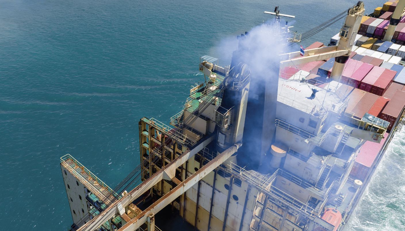
Floating on air
Another tool in the box of the marine architect is to utilize air lubrication at the hull/water interface, where viscous drag and hydrodynamic friction can be reduced. New developments have achieved significant reductions in energy consumption and therefore in emissions.
A significant attraction of air lubrication is that it is fuel-agnostic, so it can further reduce energy consumption and emissions with any alternative propulsion strategy. Most air lubrication systems (ALS) also can be retrofitted to existing vessels, with additional time in dry dock numbering a few days. In the last few years, static air films and dynamic air flow have been tested for their ability to reduce drag and energy loss.
Salvinia effect
The Salvinia effect was discovered at the start of the 21st century by botanist Wilhelm Barthlott and colleagues at the University of Bonn and the physicist professor Thomas Schimmel and his team at the Karlsruhe Institute of Technology (KIT).
2 It describes how certain plants trap a gas layer at the surface of their leaves when submerged in water, allowing respiration and photosynthesis to continue. The effect was developed for applications by Schimmel and colleagues at KIT.
Salvinia is a genus of floating fern, often found in the tropics.
Salvinia molesta is one of the most damaging invasive plants, as it can grow extremely quickly. It is thought that the air layer over the leaf allows the plant to continue respiring or photosynthesising as the leaf is submerged by other leaves growing over it. Such rapid growth often blocks water courses. In nature, friction does not appear to be a feature of the effect
(see Figure 1).3
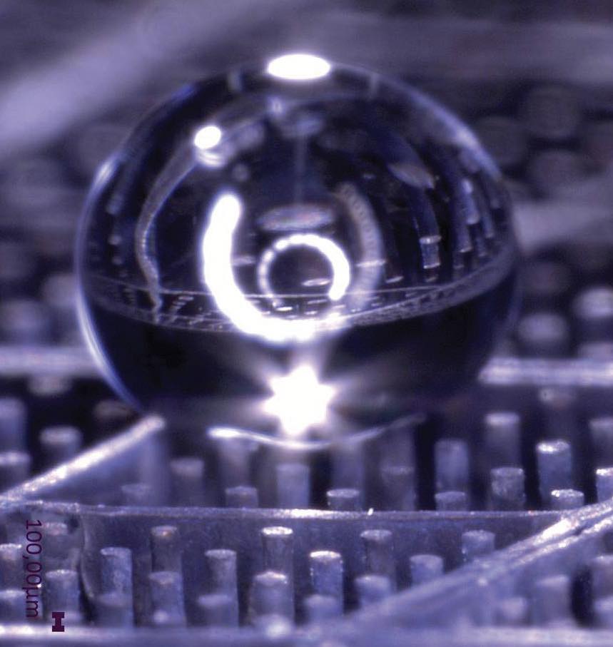
Figure 1. Water droplet sitting on AIRCOAT structure. Figure courtesy of Thomas Schimmel Group – KIT.
Further investigation by Barthlott, Schimmel and their colleagues
4 concluded that hydrophilic tips on the pillars of the plant leaves held water tightly, forming a tent-like structure over the surface of the leaf, holding the air in the superhydrophobic layer and preventing the escape of bubbles. When hydrophilic tips were added to the artificial film structures, they have proven to be able to retain an air layer for more than five years when immersed in water. “There is a permanent equilibrium between the air dissolved in the water and the air layer. If part of the air (in the air layer) is lost, it is restored from the air in the water,” says Schimmel.
Following these successes in the laboratory, Schimmel and collaborators assembled the AIRCOAT consortium to investigate and prove the benefits of films in real-life situations (
https://AIRCOAT.eu/). AIRCOAT was funded by the European Union’s Horizon 2020 research program between 2018 and 2022 with the intention of developing a biomimetic technology that traps air under water, forming a thin and permanent air layer between the hull of any water-going vessel and the water. They produced a foil that could be applied to the hull of any vessel and tested it in sea trials on a small research vessel and a container ship.
The foil contains domains (called compartments by Schimmel) of superhydrophobic pillars topped by slightly tapered discs that resemble mushrooms in high resolution SEM images and trap air
(see Figure 2).
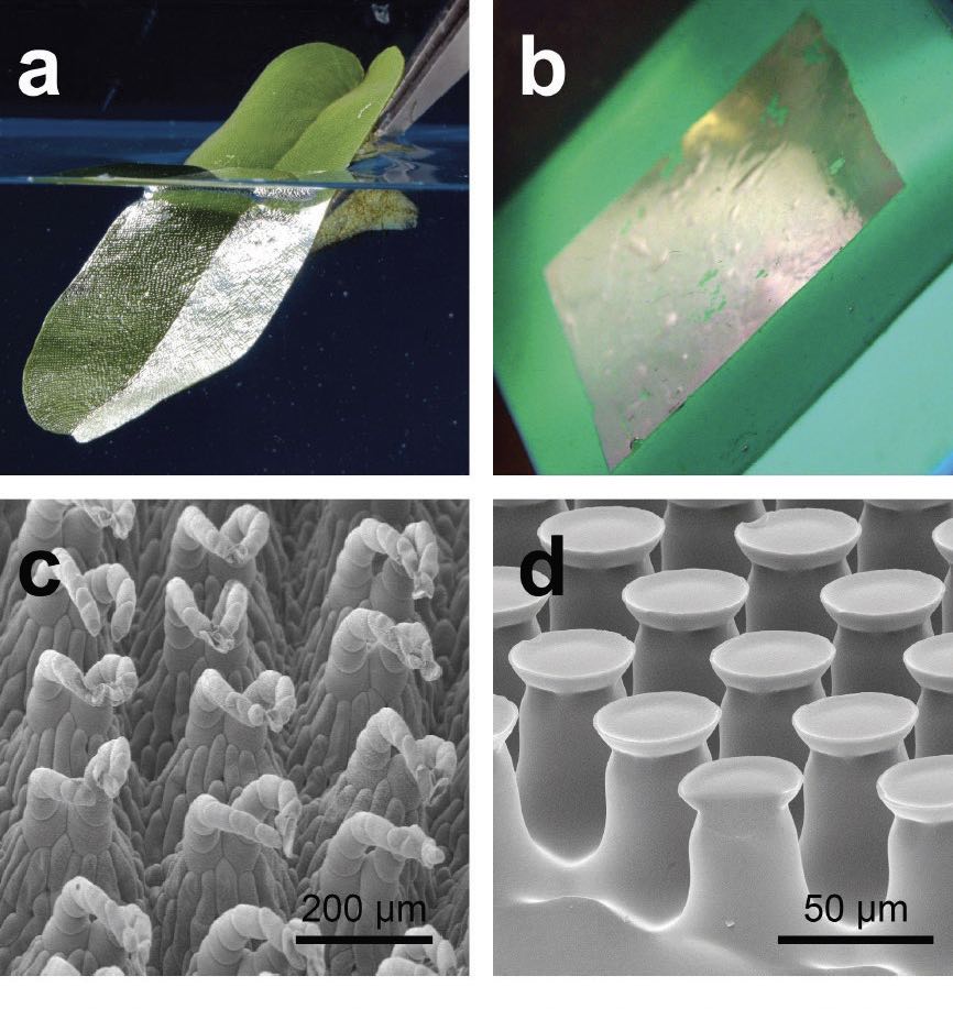
Figure 2. Biological role model and biomimetic air retaining surfaces. (a) Leaf of the floating fern Salvinia oblongifolia submerged in water. The silvery shine indicates the kept air layer. (b) Elastomer foil covered with mushroom-shaped surface microstructures (MSM) submerged in water. MSM-surfaces were glued to a green silicon surface to enhance contrast. Like on the biological role model, the silvery shine indicates the kept air. (c) SEM image of the surface structure of the Salvinia leaf. (d) SEM image of the MSM. Figure courtesy of Thomas Schimmel Group – KIT. Ref. 6: Mail, M., Walheim, S., Schimmel, T., Barthlott, W., Gorb, S. N. and Heepe, L. (2022), “Dry under water: air retaining properties of large-scale elastomer foils covered with mushroom-shaped surface microstructures” Beilstein J. Nanotechnol., 13, pp. 1370-1379, https://doi.org/10.3762/bjnano.13.113.
“The compartments on the centimeter scale prevent the air layer moving along the hull, while the original millimeter-scale pillars have meanwhile been replaced by much smaller structures on the micrometer scale, better able to withstand flow at the higher pressures of real-life operation. And the air pressure in the air compartments helps to stabilize the air film against fluctuations of pressure
(see Figure 3),” Schimmel explains.
4,5 This requires smaller pillars in a denser array on the foil surface.
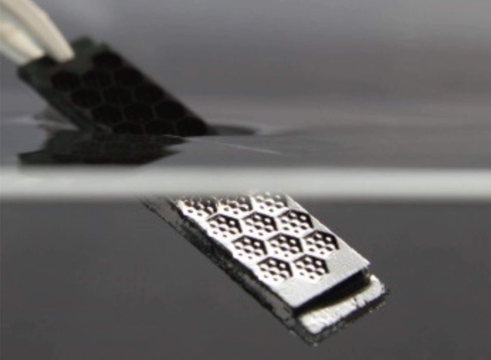 Figure 3. Progress toward technological air-retaining surfaces: silvery reflectance of the air layers under water on a completely black sample. Figure courtesy of Schimmel Group, KIT.
While the microstructures have become smaller, the macrostructures are now bigger, as the few square centimeters of film produced in a laboratory have evolved into kilometers of film produced on commercial equipment for the sea trials.
6
The foil for the sea trials was applied as a majority coating on a 10-meter research vessel (small strips of the hull were left uncovered as controls) and a partial coating of 15 square meters on the hull of a 300-meter-long container ship. The small boat experiment showed that the air layer remained intact during the trials. Now the researchers will monitor the foils on the vessels for mundane but essential observations like whether the foils remain attached to the hull.
The air film itself is expected to reduce friction and drag directly as the ship sails through the water, but the biggest frictional benefit could result from it reducing biofouling (the attachment of marine organisms, such as barnacles, seaweed and other microorganisms)
7 and corrosion. This indirect benefit arises because both biofouling and corrosion roughen the hull surface, leading to turbulence and increased drag. Schimmel emphasizes: “The advantage of air coating is that the ship is surrounded by a permanent layer of air—the ship remaining dry under water—and the permanent hull of air does not only result in drag reduction but, at the same time, provides a barrier against fouling, corrosion and toxic release from the ship hull.”
A further benefit of reducing fouling is that toxic chemicals used in marine paints and coatings can be discontinued, with consequent environmental benefits for the oceans and health benefits for those employed at shipyards. Biofouling is estimated to be responsible for an estimated $60 billion in additional fuel and maintenance costs in the global marine fleet.
8
Nils Hagemeister of Fraunhofer CML in Hamburg, Germany, part of the AIRCOAT project, modeled the AIRCOAT film on a Korean container ship (KCS) hull, a 1/32 scale model (and derived numerical model) developed by the Maritime and Ocean Engineering Research Institute, now the Korea Research Institute of Ships and Ocean Engineering (KRISO) (
http://www.kriso.re.kr/eng/). KRISO has made available data sets to describe standardized hulls, propellers, rudders and other submerged features to facilitate computational fluid dynamics (CFD) studies.
9,10 These models are often used when marine architects assess new ship designs for, say, load distribution, energy efficiency and performance in expected sea conditions.
Their models showed reductions in total resistance of 3.4% to 9.3% in various scenarios for a 230-meter-long vessel when traveling at 17.9 knots. “Our modeling showed that the wall shear stress of an AIRCOAT-coated hull is reduced most in the areas of the hull that have the highest wall shear stress on an uncoated hull,” says Hagemeister.
Experimental results now indicate that much higher values of drag reduction are achievable. Experiments performed with the artificial air-retaining surfaces developed and produced in Schimmel’s group at KIT reached drag reduction values of up to 59% in flow channel experiments performed at the Hamburg Ship Model Basin, a leading maritime testing facility.
Further sea trials would be required to demonstrate the experimental and modeled energy savings.
Flowing microbubbles
Several companies are promoting dynamic ALS that create a permanent flow of microbubbles along the flat bottom of a vessel. These systems are possibly less deeply studied than the AIRCOAT system but are mostly at the commercial stage, having been sea trialed in various real-life systems. Early adoption has probably been aided by the active nature of the lubrication. The effect of turning the air compressors on and off can be measured many times during a voyage where all other variables are essentially fixed.
Several sea trials have taken place in the 21st century.
11 As much literature claims that a dynamic ALS is only effective on the flat bottom of a vessel, one of the notable sea trials (albeit short) was that with a slender hull form ferry, where efficiency gains of 5% were reported.
12
Three elements, three regimes
There are two common ways to describe resistance to movement of a vessel through water; each has three elements. Engineers tend to think of form, wave and viscous resistance (analogous to drag if considering air as the fluid). Academics refer to pressure resistance, viscous resistance and viscous pressure resistance. Air lubrication works only on the viscous resistance. So, it is important to model all elements—especially for retrofits—where a hull shape optimized for form resistance in the absence of air lubrication may be suboptimal for air lubrication, due to sloping sides, for example.
According to the American Bureau of Shipping,
11 for higher speed displacement vessels, the frictional resistance is approximately 40%, but for low-speed displacement vessels, the frictional resistance is the dominant contributor and can reach 85% of the total resistance. Hagemeister explains that this doesn’t mean that the greatest benefits are at low speeds. “As frictional resistance increases with the square of speed, the frictional resistance is highest at high speeds. So, in absolute terms we would expect larger gains from air lubrication at higher speeds.” This is borne out by published sea trial data using a dynamic ALS.
13
Pieter Kapteijn of Marine Performance Systems (MPS)
14, based in Rotterdam, the Netherlands, says, “Air lubrication works best on ships with large flat bottom areas, sailing at design speeds and low drafts.”
There are three regimes for dynamic air lubrication. Air layer drag reduction (ALDR), while reducing drag by close to 100% in ideal situations, requires very high volumes of air, so has a diminishing return due to the energy required to power the air compressors. There has been at least one trial of the Air Chamber Energy Saving (ACES) system. Chambers were created on the flat bottom of a vessel and air fed in to separate the water from the hull. Energy savings of 15% were claimed in trials on inland waterways,
15 but doubts have been expressed about the ability to maintain the air layer in coastal waters or open sea.
Bubble drag reduction (BDR) achieves only small drag reductions, again making the return on investment in installation too small. So, most commercial applications focus on the transitional regime, where drag reductions of up to 80% are possible
(see Figure 4).
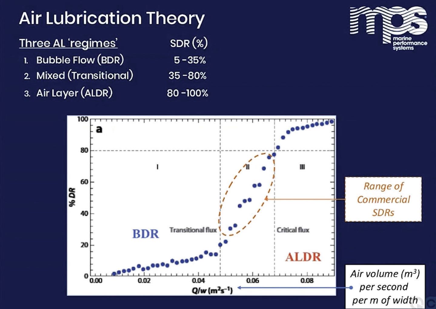 Figure 4. Three regimes of air lubrication: BDR = bubble drag reduction, ALDR = air layer drag reduction. Commercial activities are concentrated in the transition regime, labelled II. Figure courtesy of Elbing, B. R., Winkel, E. S., Lay, K. A., Ceccio, S. L., Dowling, D. R. and Perlin, M. (2008), “Bubble-induced skin-friction drag reduction and the abrupt transition to air-layer drag reduction,” J. Fluid Mech., 612, pp. 201-236.
The effectiveness of an ALS can be described by the specific drag reduction (SDR): the reduction in resistance while moving 1m
2 of the wetted surface (covered by the air layer) at ship speed.
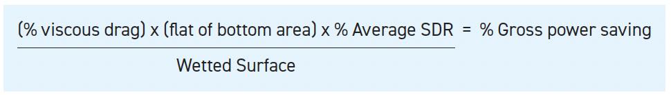
SDR is used in the calculation below of net fuel savings.
The net power saving is calculated by subtracting the energy required to power the air compressors and any associated auxiliary equipment. “In the transitional regime, we see two to three times the reduction in overall energy used to move the vessel compared to that consumed to generate the air layer,” says Kapteijn. “We believe that the physics (of air lubrication) are not completely understood,” he continues. But understanding the physics is not a major obstacle to progress. The systems work and have relatively short payback periods. Such understanding may follow and inform refinement of ALS, but they are not required for commercialization.
Experiment and modeling
Possible causes of the benefits include reduced friction or reduced turbulence of the boundary layer. Many proponents talk of microbubbles, as theory says small bubbles are beneficial. However, by the time they have traveled a few meters aft of the injection ports, bubbles have had opportunities to coalesce or break up, and the actual bubble size is dictated by the turbulence in the boundary layer at that point on the hull. MPS has patented fluidic oscillation as a means for generating bubbles with diameters of 4-6 mm
(see Delivering the air bubbles section). These were shown to be effective first at the Technical University of Delft in the Netherlands and then in sea trials. A significant consideration in the final design was the practicality of manufacturing the fluidic oscillators from molded acrylonitrile butadiene styrene (ABS) thermoplastic.
Various studies or modeling exercises can show broad brush agreement with experiment, with the interesting observation from the lubricants field that, in Figure 5, the parameter q (critical air flux) has the units of kinematic viscosity and U is the speed of the injected air stream.
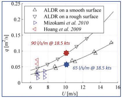 Figure 5. Critical air flux required to establish air layer drag reduction on a smooth and a rough flat plate. Figure courtesy of Elbing, B. R., Mäkiharju, S., Wiggins, A., Perlin, M., Dowling, D. R. and Ceccio, S. L. (2013), “On the scaling of air layer drag reduction,” J. Fluid Mech., 717, pp. 484-513.
CFD is a powerful tool when seeking to understand and optimize the flow of bubbles. However, the computing power required to model the flow accurately is another obstacle to properly understanding how ALS works. For example, there are millions of bubbles a few millimeters in diameter flowing across the tens or hundreds of square meters of a flat bottom. Pressure (loaded vessel versus ballasted), surface roughness or bubble distribution through the depth of the layer also are factors to be modeled. According to Kapteijn, “This is turbulent, multi-phase flow, so is very difficult to model.”
Gaining understanding to inform these models from laboratory-based systems also is not simple, as small-scale models in tanks can’t reproduce the pressures or scales of large vessels, fully laden or the relationships between bubble size and vessel size. The scaling factors also are different for bubble flow and model vessels in towing tanks, so the two cannot be modeled together using small-scale experiments, and a lot of approximation is added to any modeling exercise.
Milad Armin, senior lecturer at Liverpool John Moores University and executive director of Enki Marine Technology Consultancy, based in Liverpool, England, has attempted to model the flow of bubbles underneath a horizontal plate. He began by attempting to model flow across a 7-meter section of a KCS hull. “We moved from a KCS hull as it was less computationally expensive to simulate bubbles flowing underneath a plate measuring 2 x 8 meters,” says Armin. “We have successfully replicated our observations across different plate sizes from 0.5 meters to 80 meters.”
Reynold’s-averaged Navier–Stokes equations helped him describe the turbulent, high velocity fluid flows. The Reynolds number is a dimensionless quantity that helps to scale down a full-size phenomenon while capturing the true physical characteristic of the flow, such as its inertia and viscosity. At high Reynolds numbers the flows tend to be turbulent. Navier–Stokes equations are partial differential equations that describe the motion of viscous fluids.
Armin’s methods are computationally efficient because they estimate what is happening in the boundary layer. “Fortunately, most of the magic happens in the boundary layer,” says Armin. This is where the (micro)bubble interactions occur. Large eddy simulations or direct numerical simulations are highly computer-intensive, so academic researchers often restrict themselves to small flat plates or a few bubbles.
He selected conditions to represent a 200-meter container vessel sailing at between 16 and 24 knots with turbulent and high velocity bubble flow along the plate. The key parameter here is the Froude number— a relationship between a ship’s length and velocity often used in ship design.
16 Friction resistance is a high proportion of the overall resistance for vessels with a low Froude number, such as bulker carriers, tankers and container ships.
17
Armin’s first success was to model the entrapment of bubbles in the boundary layer as they traveled along the plate, which was affected by turbulence and buoyancy. His models also successfully captured “swirls” as bubbles escaped past the sides of the plate and described spiral motion, rather than simply floating away under their own buoyancy (
see Figure 6).
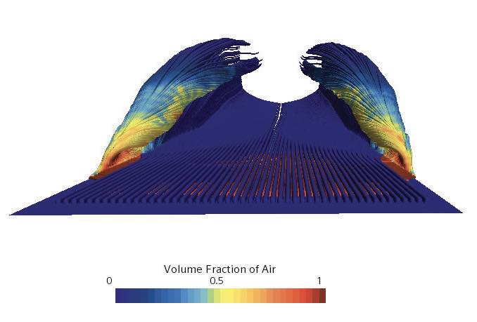
Figure 6. Swirl viewed from top front of plate. Figure courtesy of Enki Marine Consultancy.
“We were able to define a parameter that successfully modeled the change in drag reduction related to ship speed, ship draft, volume fraction of air in the boundary layer and the density of the air/water mixture,” says Armin.
These are relatively small steps on the way to modeling the whole of a vessel bottom, where the flat bottom surface of a bulk carrier can be several hundred meters long and tens of meters wide. Once flat plates and flat bottoms can be modeled, aspects that must be factored in relate to the shape of the hull, propellers and rudder and the most likely sea conditions the vessel will face. Even the largest vessels pitch and roll, which affects the macroscopic flow of the bubbles, including loss around the sides of the hull. To optimize bubble sizes and flow rates for dynamic ALS, all these parameters should be expressed numerically.
Delivering the air bubbles
There are two generic means of delivering air flows: through orifices or cavities in the hull of the vessel or from dispersing equipment attached to the hull. All require interventions into the hull. So, when retrofitting, significant engineering time must be spent on finite element analysis to establish that the integrity of the hull is still to the required standards. This is part of the recertification process that can be time consuming and presents additional cost.
Other considerations on installation are the effects on the center of gravity of the vessel and the power consumption of the ALS equipment. Locating the compressors close to the injection orifices can change the weight distribution of the vessel when ballasted and loaded. While the energy payback according to Kapteijn is 3:1 propulsion energy saved relative to air compressor energy consumed, the ship’s power distribution systems must be able to supply the compressors with the required power.
One company uses “wings” of fluidic oscillators along the flat bottom. The second and subsequent wings replenish the bubble film when this is lost due to rolling, trimming or turning and allow zonal distribution of air. Each wing section requires one or two 8-10-inch holes in the hull, which do not compromise the structural integrity of the vessel, so installation does not require recertification.
The wings are fluidic oscillators.
18 Air is forced into an air channel in each wing, where the internal shape causes fluidic oscillation,
19 which creates a layer a few centimeters thick of microbubbles of 4-6 millimeter diameter
(see Figure 7).
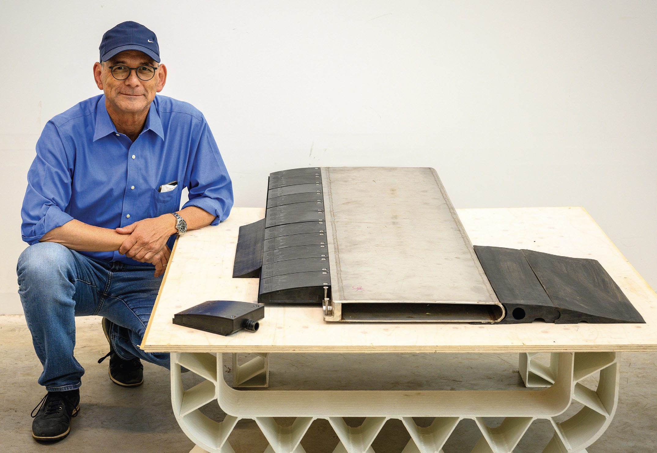 Figure 7. Peter Kapteijn with most of one wing of the FluidicAL system. He is on the aft side of the installation. The fluidic oscillators are nearest to him, an air chamber in the middle and tapered units to minimize turbulence as the vessel moves forward are to the right. Figure courtesy of Peter Kapteijn.
Practical experience
Figure 7. Peter Kapteijn with most of one wing of the FluidicAL system. He is on the aft side of the installation. The fluidic oscillators are nearest to him, an air chamber in the middle and tapered units to minimize turbulence as the vessel moves forward are to the right. Figure courtesy of Peter Kapteijn.
Practical experience
Commercial systems have now been installed or retrofitted on cruise liners, rollon/ roll-off (Ro-Ro) ferries and a variety of bulk, LNG and crude oil carriers.
20, 21, 22, 23 In addition to fuel consumption savings, some trials measured reductions in particulate and other emissions to air, which were reduced at least in proportion to the savings in fuel. This is probably a result of the engine operating for longer in its design envelope.
A sea trial was conducted on a small bulk carrier sailing between Duisburg in Germany and the Humber estuary in the UK. This meant a mix of river, coastal and open sea shipping. The three-month trial was able to demonstrate 9% average fuel savings, “and we know how to squeeze another 2% out of the system,” says Kapteijn. They also were able to demonstrate 3%-6% speed increases when the ALS was activated with the vessel sailing at its design speed.
A significant benefit for crew, the marine environment and even people living and working near ports is that dynamic ALS reduces noise. During a sea trial aboard a 210,000 deadweight bulk carrier sailing between Singapore and Australia, reduction in vibration was very noticeable. “You could feel the vibration of almost every surface stop when the ALS was activated,” says Kapteijn. The Port of Vancouver in Canada has offered discounts on harbor fees since 2017 to vessels meeting voluntary environmental best practices that reduce emissions, underwater noise and other environmental impacts.
24 Other ports offer equivalent incentives.
Concerns
The issue raised most often by potential customers, according to both Armin and Kapteijn, is cavitation, in the context of potential damage to the propeller.
“This is easily addressed,” says Kapteijn. “There isn’t any cavitation.” Cavitation occurs when low pressure, vapor-filled bubbles collapse violently. In ALS the air in the bubbles is at the same pressure as the water, so there is no collapse.
The interaction of the bubbles with the propeller is a much more relevant issue— but not from the perspective of cavitation. Successfully extending the bubble layer along the full length of the hull risks feeding the propeller with unsteady flow. “This is the real concern. Not cavitation,” says Armin. “We should be more concerned about reducing the efficiency of our propulsion system by feeding it a two-phase flow. This is counterproductive compared to what we are trying to achieve” with air lubrication.
It is possible that the torque produced by the propeller could be reduced by the bubble flow.
25
A third issue is biofouling, with a perception that aerating the water in the boundary layer could enhance algal growth. In fact, dynamic air lubrication is antifouling. One year after installation, some oscillators were recovered from the small bulk carrier that operated between Germany and the UK, and they were clean. The sea trial had lasted three months, although the ALS was used after that. Kapteijn is sure that the benefits are due to dynamic ALS creating an aerobic environment, rather than being due to the air flow. Some companies are investigating a purge mode for use in harbors to discourage the attachment of organisms, where the system creates a very small flow of bubbles.
The future
As air lubrication is fuel-agnostic, delivering fuel and emissions savings regardless of the means of propulsion, many consider that it has a significant role in moves to decarbonize shipping. As well as allowing life-extension of existing vessels by keeping them compliant with IMO regulation
(see IMO Decarbonization), payback times on energy use are below three years, reducing as fuel prices soared in 2022, and could drop below two years when carbon pricing is introduced.
During the trial phases, retrofitting has been the order of the day, but new-build vessels are expected to enter service in 2023. Systems fitted to new build vessels can be optimized far more than the retrofits that have been used in demonstrations. “As a newbuild ALS would be integral to the design of the vessel, it should be easier and more cost effective to install,” says Kapteijn, who adds, “We are over the hump with respect to adoption of the technology. Rising fuel prices and legislation to reduce emissions are coming together to create a perfect situation for adoption.”
REFERENCES
1.
IMO (2020), “Fourth greenhouse gas study 2020.” Available
here.
2.
Barthlott, W., Schimmel, T., Wiersch, S., Koch, K., Brede, M., Barczewski, M., Walheim, S., Weis, A., Kaltenmaier, A., Leder, A. and H.F. Bohn, H. F. (2010), “The Salvinia paradox: Superhydrophobic surfaces with hydrophilic pins for air retention under water,”
Advanced Materials, 22 (21), pp. 2325–2328.
3.
https://en.wikipedia.org/wiki/Salvinia_ effect. The first experimental films consisted of columns on a hydrophobic film. While they repelled water droplets, showing a classic high contact angle, they lost air as bubbles after a few minutes under water.
4.
Gandyra, D., Walheim, S., Gorb, S., Ditsche, P., Barthlott, W. and Schimmel, T. (2020), “Air retention under water by the floating fern Salvinia: The crucial role of a trap- ped air layer as a pneumatic spring,”
Small, 2003425.
5.
Air Spring Effect at
https://aircoat.eu/salvinia-effect/.
6.
Mail, M., Walheim, S., Schimmel, T., Barthlott, W., Gorb, S. N. and Heepe, L. (2022), “Dry under water: air retaining properties of large-scale elastomer foils covered with mushroom-shaped surface microstructures,”
Beilstein J. Nanotechnol., 13, pp. 1370-1379,
https://doi.org/10.3762/bjnano.13.113.
7.
Schimmel, T. (2020), “Friction reduction and antifouling with bionic coating,” in: acatech DISCUSSION –
National Academy of Science and Engineering, Eds.: Fratzl, P. Jacobs, K., Möller, M., Scheibel, T., and Sternberg, K., Munich, 59.
8.
Salta, M., Wharton, J. A., Stoodley, P., Dennington, S. P., Goodes, L. R., Werwinski, S., Ugar, M., Wood, R. J. K. and Keith, S. R. (2010), “Designing biomimetic antifouling surfaces,”
Phil. Trans. R. Soc. A., 368, pp. 4729-4754,
http://doi.org/10.1098/rsta.2010.0195.
9.
Van, S. H., Kim, W. J., Yim, G. T., Kim, D. H. and Lee, C. J. (1998b), “Experimental investigation of the flow characteristics around practical hull forms,” Proceedings 3rd Osaka Colloquium on Advanced CFD Applications to Ship Flow and Hull Form Design, Osaka, Japan.
10.
Kim, W. J., Van, D. H. and Kim, D. H. (2001), “Measurement of flows around modern commercial ship models,” Exp. in
Fluids, 31, pp. 567-578.
11.
American Bureau of Shipping (2019), “Air lubrication technology.” Available
here.
12.
Available here.
13.
Available here.
14.
Marine Performance Systems was acquired by Alfa Laval, a global supplier of heat transfer, centrifugal separation and fluid handling solutions, in March 2023. Company names and personnel titles in this article are accurate at the time of publication.
15.
Available here.
16.
See
here and, in particular, part of the course literature
here.
17.
Available here.
18.
Woszidlo, R. and Krüger, O. (2022), Editorial for the special issue on “Fluidic oscillators - devices and applications,”
Fluids, 7 (3), 91,
https://doi.org/10.3390/fluids7030091.
19.
Available here.
20.
Available here.
21.
Available here.
22.
Available here.
23.
www.capitalpplp.com/about-us
24.
Available here.
25.
Kawakita, C. (2013), “Study on marine propeller running in bubbly flow,” Proceedings of the Third International Symposium on Marine Propulsors - smp13, 405-411, ISBN 978-0-646-90334-7.