In-situ tribometry for understanding the near ultralow wear of neat PTFE
By Kian Kun Yap and Marc Masen | TLT Fellowship Research March 2023
Tribology Group, Department of Mechanical Engineering Imperial College London, South Kensington Campus, London SW7 2BX, United Kingdom
Editor’s Note: This month TLT profiles the 2022 recipient of The Elmer E. Klaus Fellowship, Kian Kun Yap (Imperial College London). The Klaus Fellowship, along with The E. Richard Booser Scholarship, are awarded annually to graduate and undergraduate students, respectively, who have an interest in pursuing a career in tribology. As a requirement for receiving an STLE scholarship, students are given the opportunity to participate in a tribology research project and to submit a report summarizing their research. For more information on the Elmer E. Klaus Fellowship, visit www.stle.org.
Yap is a final-year doctoral candidate at the Tribology Group of Imperial College London. He works with STLE members Dr. Marc Masen and Dr. Janet Wong on the tribology of high-performance polymers. He specializes in the application of advanced in-situ tribometry techniques to characterize the development of polymer transfer films. His project is funded by the Engineering and Physical Sciences Research Council, United Kingdom (EPSRC) and supported by STLE member Dr. Lucas Amspacher from DuPont de Nemours Inc., U.S. Yap can be reached at kkyap@imperial.ac.uk.

Kian Kun Yap
Abstract
Despite the low friction, the notoriously high wear rate of polytetrafluoroethylene (PTFE) makes it unsuitable as a tribomaterial in its neat form. This contribution investigates the possibility of PTFE achieving an ultralow wear rate (< 10-6 mm3/ Nm) without the aid of fillers. Two in-situ pin-on-disc tribometry techniques, namely spatiotemporal mapping and optical microscopy, are used to study the transfer and wear mechanisms of PTFE when slid against AISI 304. Results demonstrate that a near ultralow wear rate as low as 2×10⁻⁶ mm3/Nm can be realized simply by pre-oxidizing the metal counterface. The authors are currently working on measuring the height profiles of PTFE transfer lumps in real time using in-situ digital holographic microscopy. Preliminary results show that the refractive index of these lumps is not constant, which contradicts the common practice in polymer tribology, which assumes a constant refractive index.
Introduction
Polymer-metal tribo-pairs are used in machine elements such as bearings, bushings and gears as a replacement for traditional metal-metal tribo-pairs, especially in applications where liquid lubrication is unfavorable, e.g., in aerospace and energy industries where high temperature and/or vacuum can evaporate the lubricants and in food, pharmaceutical and semiconductor industries where tolerance for contamination is stringent. This is because polymer-metal tribo-pairs are usually less susceptible to seizure and have a low coefficient of friction in dry sliding.1 These inherent properties give polymers the ability to self-lubricate and it is generally accepted that the self-lubrication is contributed by the formation of polymeric transfer layers on the metal counterface.2
One of the most popular textbook examples of self-lubricating polymers is PTFE.2 When PTFE is sheared against a metal, some polymeric material exfoliates and adheres to the metal counterface to form a thin and uniform transfer film of 5 to 10 nm thick.3 The combination of the low shear strength of the thin PTFE transfer film and the high hardness of the metal substrate results in a coefficient of friction that can be as low as 0.04. An example of this transfer mechanism is shown in a pin-on-disc sliding test conducted in situ in a scanning electron microscope in Figure 1. This transfer mechanism may seem ideal, but it only occurs within a limited range of operating conditions, one of which is a low sliding speed (< 0.01 m/s).3,4 In most real-world applications, however, the sliding speed is much higher and thick and patchy transfer lumps are formed instead of thin and uniform transfer films.5 These lumps are usually a few micrometers thick5 with the polymeric material released through subsurface failure and crack propagation.6 The coefficient of friction in this case increases to typically between 0.20 and 0.25.5
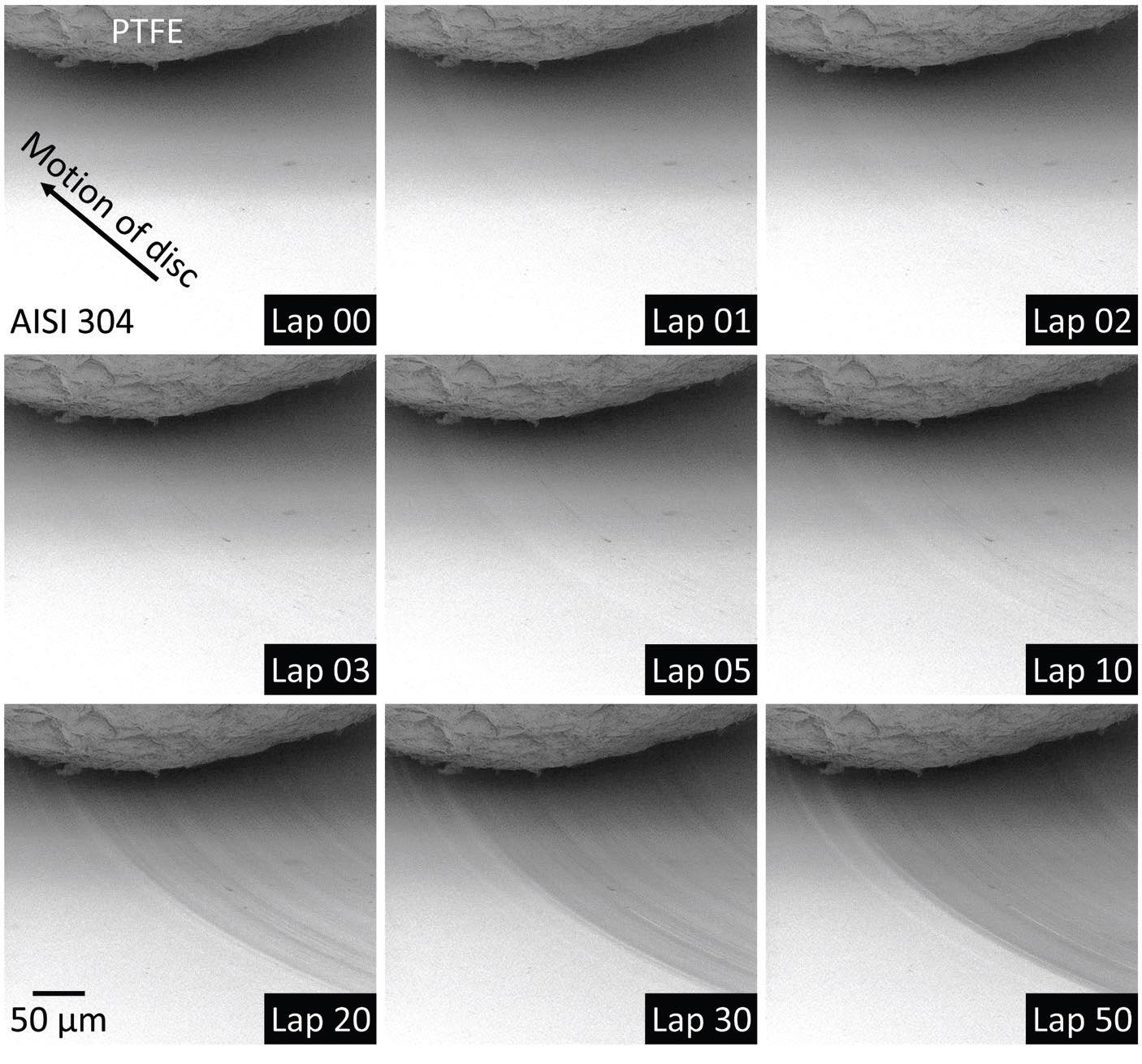
Figure 1. The gradual build up of a thin and uniform PTFE transfer film on a mirror-finished AISI 304 disc in a unidirectional pin-on-disc sliding test. The test was conducted in situ in a scanning electron microscope using an Alemnis Standard Assembly (ASA). The pin was made of a PTFE ball with a 1 mm diameter. The AISI 304 disc had a surface roughness Ra of 20 nm. The applied load was 1 N, which was equivalent to an initial mean Hertzian contact pressure of 47 MPa. The sliding speed was 152 μm/s. The disc wear track had a diameter of 1.74 mm.
Figure 2 shows the graph of specific wear rate against coefficient of friction for the unlubricated sliding of various polymers against steels. The wear rates for both abovementioned transfer mechanisms are high, usually greater than 10-4 mm3/Nm (refer to data points a and b in Figure 2).5 This is due to the constant transfer of PTFE to the metal counterface to replenish the poorly adhered films or lumps that are eventually discharged as wear debris. Over the past century, researchers have been working on improving the wear performance of PTFE by the addition of various soft and hard micro and nano-fillers, such as carbon nanotubes (CNT) and polyether ether ketone (PEEK) microparticles (refer to data points c and d in Figure 2). These fillers can readily reduce the wear rate of PTFE to 10-5 mm3/ Nm and below and some can even reach the so-called ultralow wear, which is a wear rate below 10-6 mm3/Nm.7 One of the most effective wear-reducing fillers for PTFE to date is alpha alumina nanoparticles (refer to data point e in Figure 2).8 PTFE composites with this filler usually operate at ultralow wear rates in the order of magnitude of 10-8 mm3/Nm. The filler works by promoting the tribo-chemical reaction between sheared PTFE and metals to form a brown substance called metal chelates.9 This tribo-chemical species is found both in the primary transfer film, i.e., the film that forms on the metal counterface, and in the secondary transfer film, which also is known as the back-transfer film or running film, that forms on the PTFE surface. Metal chelates improve the adhesion of transfer films and prevent direct polymer-metal contact. The coefficient of friction of PTFE composites varies a lot depending on the types of fillers used, but in general, it ranges from 0.15 to 0.25.
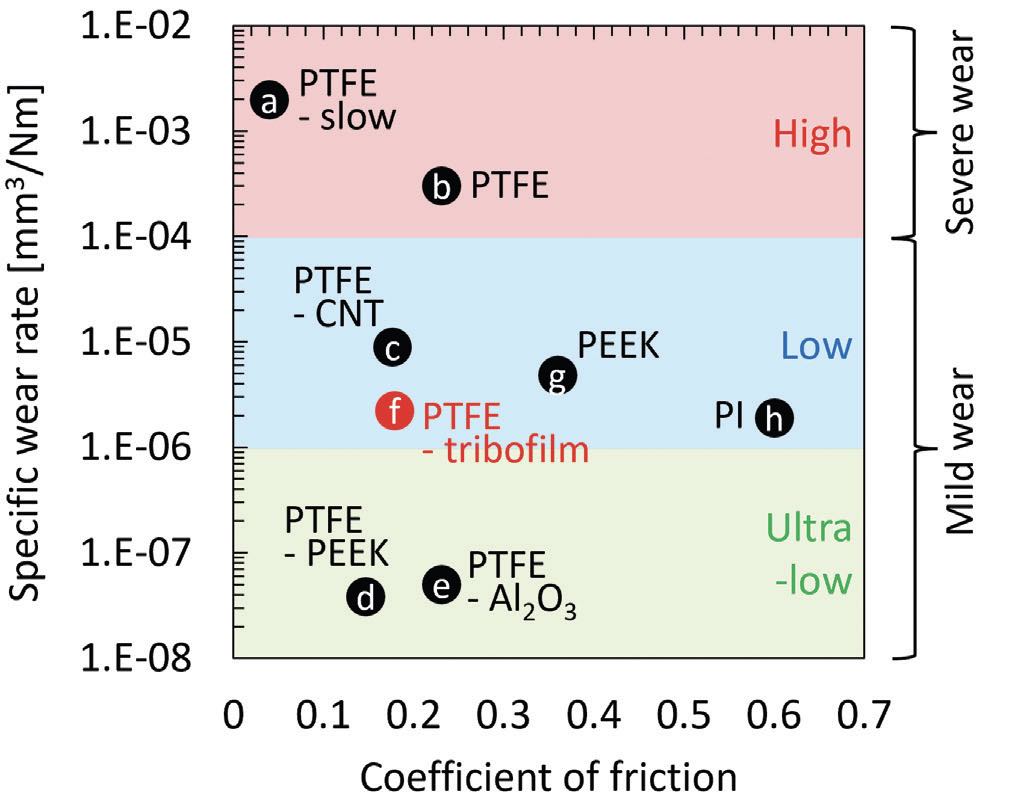
Figure 2. Graph of specific wear rate against coefficient of friction for the unlubricated sliding of various neat and filled polymers against steels. The details of the data points are listed as follows: (a) neat PTFE sliding at 152 μm/s (refer to Figure 1), (b) neat PTFE sliding at 0.06 m/s,5 (c) 20 vol% CNT-filled PTFE nanocomposite,10 (d) 40 wt% PEEK-filled PTFE microcomposite,11 (e) 5 wt% α-Al2O3-filled PTFE nanocomposite,11 (f) neat PTFE covered with a tribo-chemical-induced film (as of how this film is induced will be discussed later),5 (g) neat PEEK,7,12 and (h) neat PI.7 The red region represents a high wear rate, the blue region represents a low wear rate, and the green region represents an ultralow wear rate.
While it is undeniable that fillers can reduce wear, several drawbacks make PTFE composites less qualified candidates in some applications. Reasons include the increase in material and production costs, the decrease in recyclability and the generation of contaminants which may be hazardous to machines, humans and/or the environment. As mentioned in the previous paragraph, the formation of a tribo-chemical-induced film is the key to the ultralow wear of PTFE- based systems. This raises the question of whether this film can be formed without the aid of fillers to achieve a similar wear-reducing effect. In this article, the authors will discuss how in-situ tribometry techniques are utilized to better understand the transfer and wear mechanisms of neat PTFE and how this information is then utilized to achieve a near ultralow wear rate of 2×10⁻⁶ mm3/Nm for PTFE without the addition of fillers (refer to data point f in Figure 2).5 As a reference, this wear rate is comparable to that found in some of most wear-resistant high-performance polymers available in the market today, such as PEEK and polyimide (PI) (refer to data points g and h in Figure 2).
Methods
Polymers are usually much softer than metals and the tribological behaviors of a polymer- metal system tend to evolve constantly throughout its operation and respond less predictably compared to a metal-metal system. For this reason, the commonly used post-test and interrupted test analyses are not sufficient to pick up all potentially useful information when performing a tribological experiment on a polymer-based system. A post-test analysis, for example, tends to overlook the temporal evolution of transfer materials, while an interrupted test analysis may disturb the thermal and dynamic history of the test, causing a deviation from the originally anticipated behaviors. To address these issues, two in-situ pin-on-disc tribometry techniques, namely spatiotemporal mapping (SMA) and optical microscopy, were applied.
Detailed test procedures for this part can be found in a recent paper published by Yap et al.,5 but in brief, a pin-on-disc tribometer with a humidity-controlled chamber was used. The stationary pins were made of 8 mm diameter neat PTFE balls and the rotating discs were made of AISI 304 stainless steel. The discs were polished down to a surface roughness Ra of 20 nm. A 10 N dead weight was applied to the pin. This is equivalent to an initial mean Hertzian contact pressure of 27 MPa. The sliding speed was 60 rpm or 0.06 m/s and the wear track had a diameter of 20 mm. Each test lasted 2,000 rotations or 126 m. The vertical pin displacement and coefficient of friction were recorded. The vertical pin displacement data is used to calculate the real-time specific wear rate of the PTFE in mm3/Nm, while the coefficient of friction is plotted as an SMA.
An SMA can be plotted in various forms according to applications. In this article, the authors’ definition for an SMA is a 3D graphical representation of the coefficient of friction in which the x-axis or the spatial axis represents the position along the wear track on a disc, the y-axis or the temporal axis represents the number of repeated sliding cycles, while the z-axis or the color intensity represents the magnitude of the coefficient of friction. This technique was first introduced in the field of tribology by Fukuda and Belin in 1992 to study the accumulation and mutual transfer of adhesive wear and the delamination and spalling of coatings.13,14 Since then, there have been several works that applied this technique, typically limited to metal-metal systems.15–19 There is little literature available on the use of SMA in polymer-metal systems.
SMA enables non-disruptive, real-time, in-contact friction information at any position on the disc and at any instant of time during a test. This technique can be easily implemented in most commercial tribometers with no additional hardware required, as long as the sensors’ acquisition systems are synchronous with the disc motion. However, since it is usually plotted with friction data, it does not provide any visual information. Therefore, more insights can be obtained if the SMA technique is used complementarily to a visual-based in-situ technique. For this reason, in-situ optical microscopy was employed.
A digital optical microscope was installed on the pin-on-disc tribometer. It was placed above the disc wear track, opposite the pin. All test conditions were the same as that of the SMA test described previously except the diameter of the disc wear track was increased to 40 mm. To keep the same linear speed of 0.06 m/s as before, the angular speed was therefore decreased to 30 rpm. The number of repeated sliding cycles was kept constant at 2000 rotations, which results in a total sliding distance of 251 m. The camera is triggered by an optical switch with 50 ns rise and fall time. A micrograph was captured in every sliding cycle with an exposure time of 5 ns. All micrographs were rescaled to the same intensity range to optimize the brightness and contrast levels for better presentation.
Results and discussion
Figure 3 shows the specific wear rate of the PTFE pin and coefficient of friction for PTFE/AISI 304 sliding at different levels of humidity, in a steady state situation, in this case during the final 500 sliding cycles of the test.5 All dry tests at 5% humidity exhibit severe wear with a wear rate higher than 10-4 mm3/Nm. Tests at 50% and 95% humidity show poor repeatability, with wear results fluctuating over two orders of magnitude between the severe and mild wear regions. In the case of mild wear, wear rate as low as approximately 3×10⁻⁶ mm3/Nm is measured. The results suggest that moisture is required to achieve mild wear, but there are additional underlying factors that contribute.
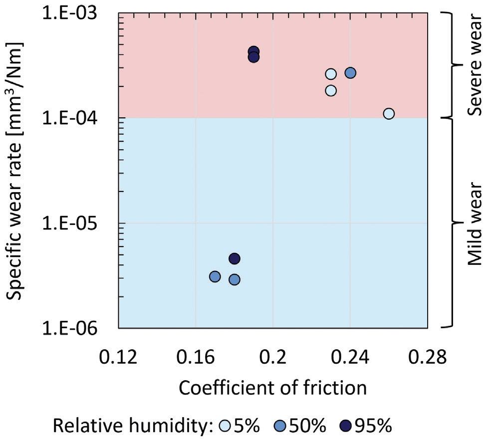
Figure 3. Graph of steady-state specific wear rate of PTFE pin against coefficient of friction for PTFE/AISI 304 sliding at different levels of relative humidity. Data points in the red region have severe wear, while those in the blue region have mild wear.5
Figure 4 shows the micrographs of two worn PTFE pins and AISI 304 discs that were tested at 5% and 50% humidity, one displaying severe wear and the other displaying mild wear.5 Severe wear is characterized by a “clean” pin surface and a disc surface heavily covered with PTFE transfer lumps, indicating the transfer of PTFE from the pin to the disc. Mild wear, on the other hand, is identified as a pin covered with a brown film and a relatively “clean” disc surface. Energy dispersive x-ray spectroscopy (EDS) analysis shows that the brown film consists of fluorine, iron and oxygen elements. This agrees with the literature and confirms that the film is a product of the tribo-chemical reaction between PTFE and steels.9 The formation of the tribofilm suggests the transfer of iron from the disc to the pin, resulting in a film that is effective at wear reduction.
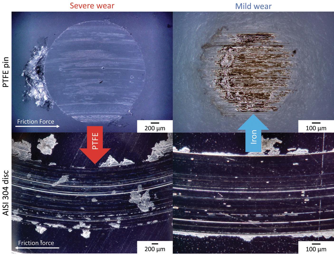
Figure 4. Micrographs of PTFE pins and AISI 304 discs with severe (at 5% relative humidity) and mild wear (at 50% relative humidity). In severe wear, PTFE is transferred from the pin to the disc to form transfer lumps. In mild wear, iron is transferred from the disc to the pin to form a tribofilm. Note that these micrographs were taken at different magnifications.5
Figure 5 shows the SMA for a PTFE/AISI 304 sliding test with severe wear.5 The color represents the coefficient of friction, ranging from 0.1 (dark) to 0.3 (light). In general, a complex pattern with rapid friction fluctuations can be observed. Zooming in to the initial 250 rotations, these friction fluctuations reveal as dark diagonal lines, indicating locally reduced friction. These diagonal lines continue throughout the sliding test and can still be spotted in the later stages of sliding; they suggest a tribological event that shifts in position on the disc wear track in repeated sliding.
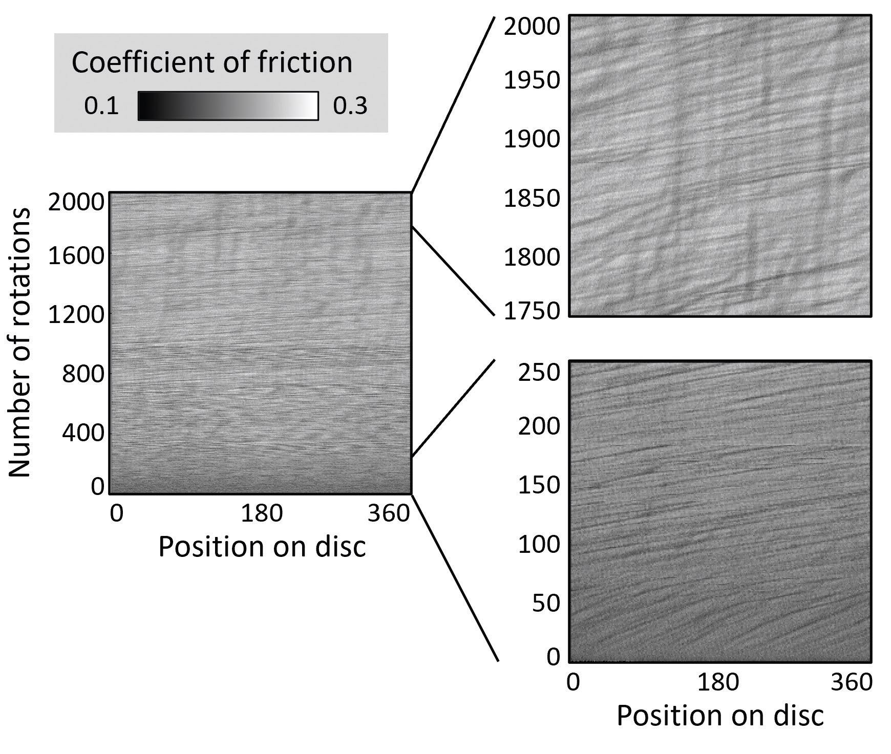
Figure 5. SMA of coefficient of friction for a PTFE/AISI 304 sliding test with severe wear (at 5% relative humidity).5
Figure 6 shows the full rotation disc wear track for the case of severe wear and the corresponding coefficient of friction for the final sliding cycle of the experiment.5 The positions where a significant reduction in friction is found match with the positions where significant PTFE transfer lumps are present near the center of the wear track as shown by the red dotted lines. This indicates that the diagonal lines with low friction found on the SMA are formed when the pin slides across the PTFE transfer lumps. When this occurs, the contact interaction is mainly between PTFE and PTFE, resulting in reduced friction. The fact that these lines are diagonal suggests that the transfer lumps are not fixed but migrate gradually along the wear track in each repeated sliding.
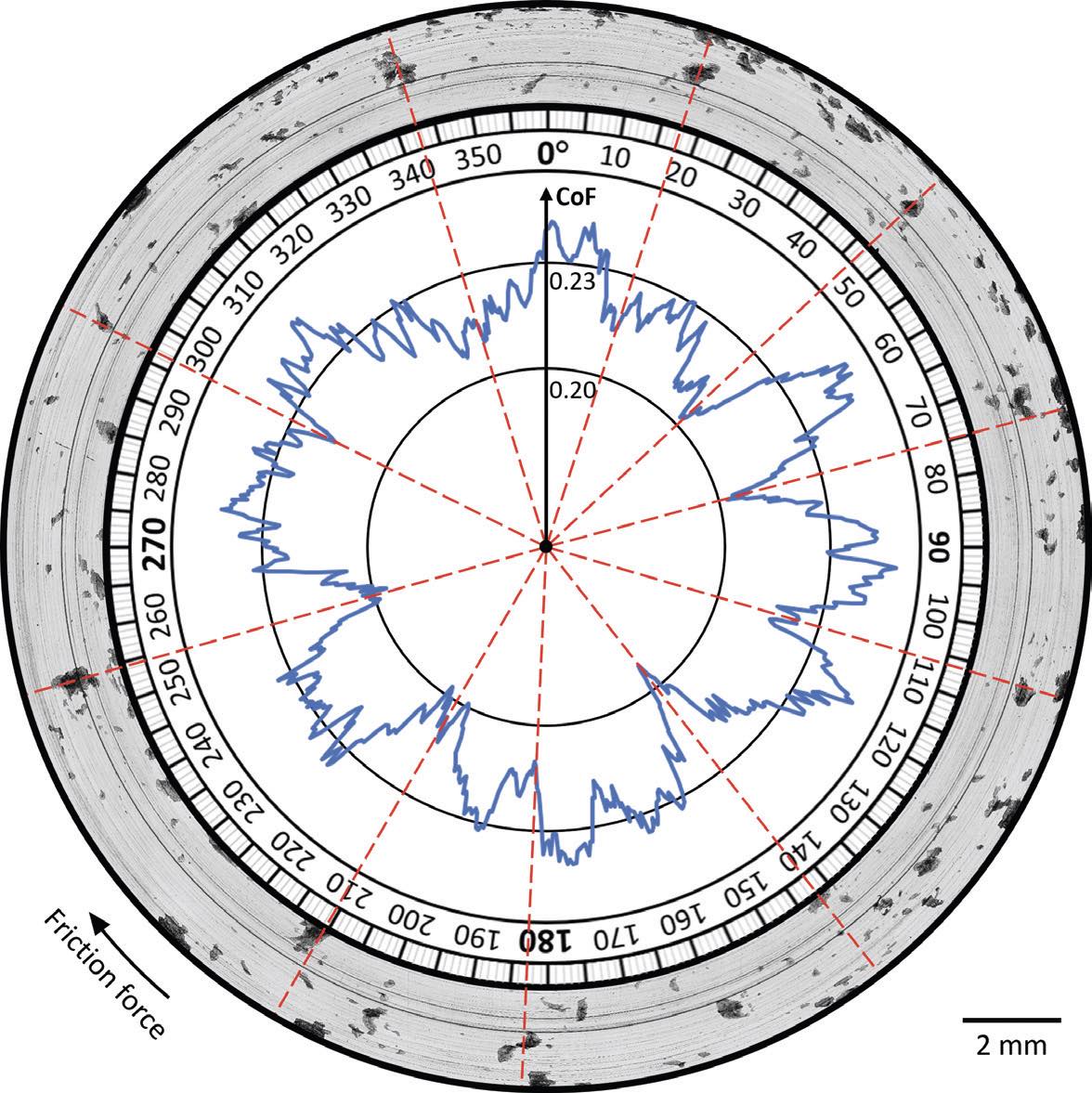
Figure 6. Full rotation disc wear track for the case of severe wear (at 5% relative humidity) and the corresponding coefficient of friction (CoF) for the final sliding cycle. The red dotted lines show that the positions where a significant reduction in CoF is found match with the positions where significant PTFE transfer lumps are present at the center of the wear track.5
This phenomenon of migration of PTFE transfer lumps on the disc wear track is visualized and further substantiated with in-situ optical microscopy. Figure 7 shows the in-situ micrographs of a disc wear track with severe wear. It can be seen that PTFE transfers to the disc counterface already in the first sliding cycle. This high transfer readiness of PTFE to metals also was reported by other researchers.9,20 Transfer lumps develop in subsequent cycles, and they migrate on the wear track, suggesting poor adhesion between the transfer lumps and the disc surface. In the later stages of sliding, the lumps grow in size. This is because the lumps are migrating at different speeds and some of them merge during repeated sliding.5 The grown transfer lumps are eventually pushed out of the wear track and discharged as wear debris, which leads to a high wear rate.
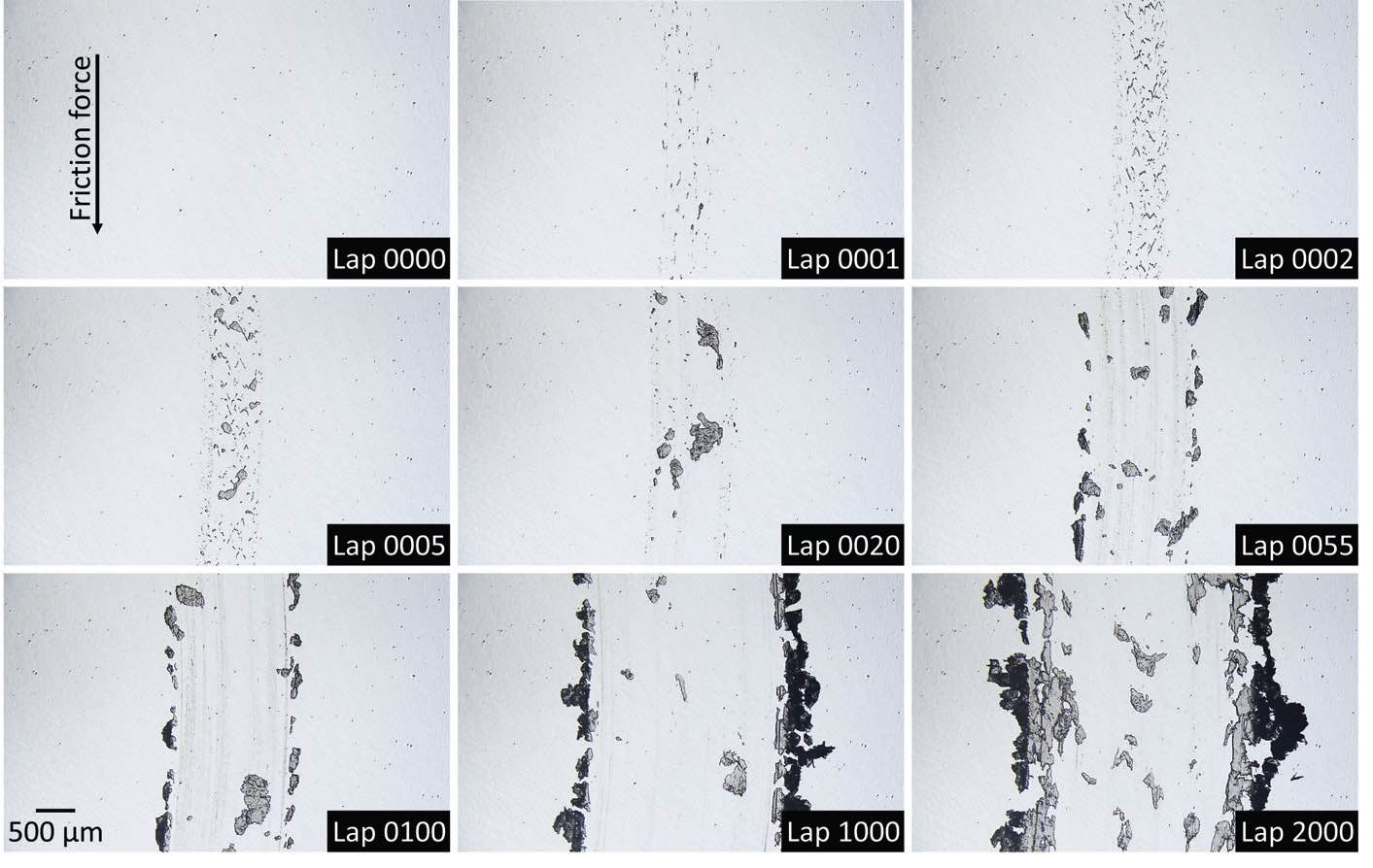
Figure 7. In-situ optical micrographs of a disc wear track for a PTFE/AISI 304 sliding test with severe wear (at 5% relative humidity).
Figure 8 shows the evolution of the coefficient of friction for a PTFE/AISI 304 sliding test with mild wear.5 In general, friction is lower compared to the severe wear case (shown in Figure 5). Zooming in to the initial 250 rotations, diagonal lines with lower friction are also found. Again, these lines correspond to the migration of transfer lumps. This is supported by the in-situ micrographs as shown in Figure 9. Unlike the severe wear case, the diagonal lines fade within the first 100 rotations and can hardly be seen in the final 250 rotations. The fading of diagonal lines correlates with the disappearance of transfer lumps on the wear track as shown in the in-situ micrographs in Figure 9.
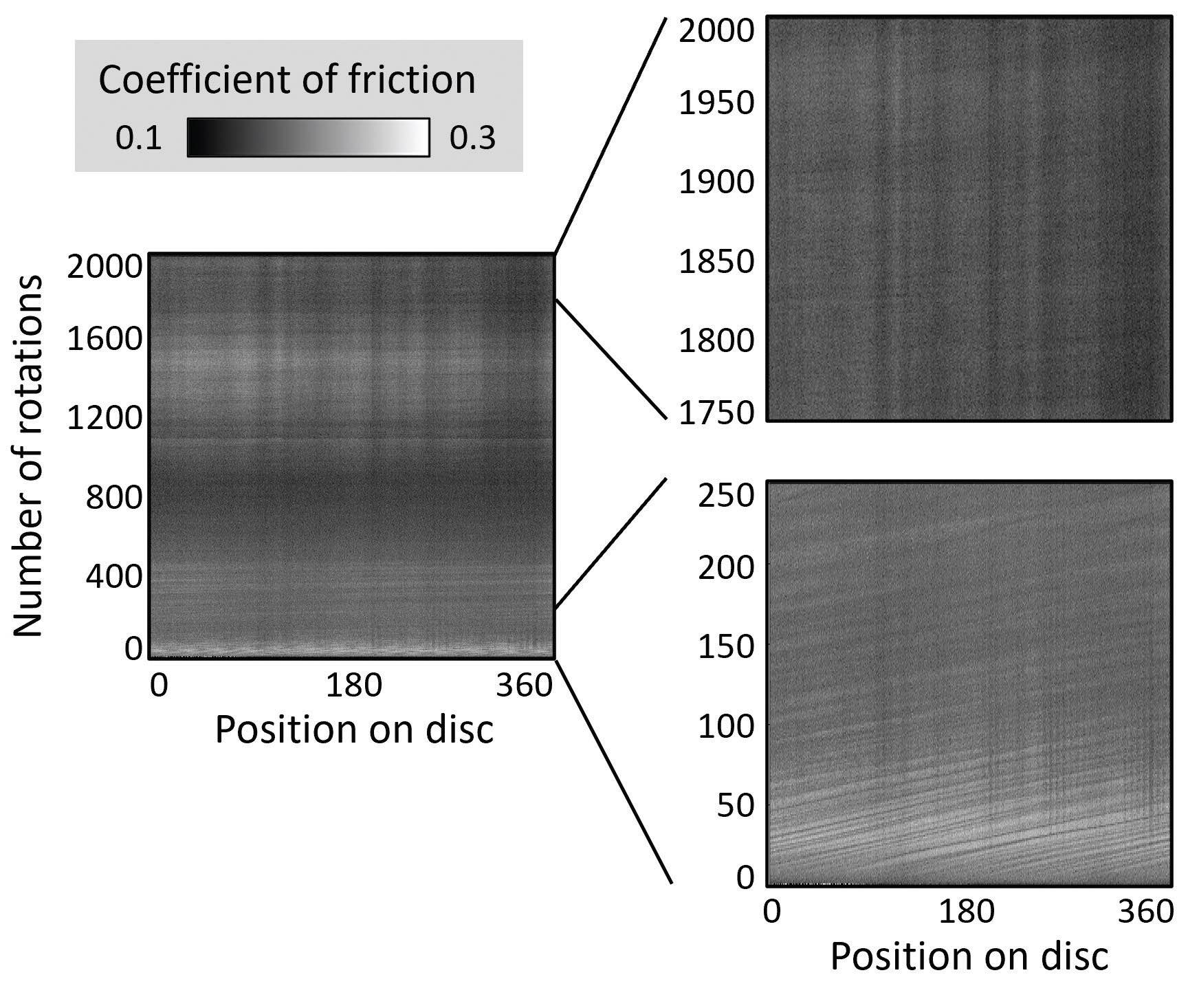
Figure 8. SMA of coefficient of friction for a PTFE/AISI 304 sliding test with mild wear (at 50% relative humidity).5
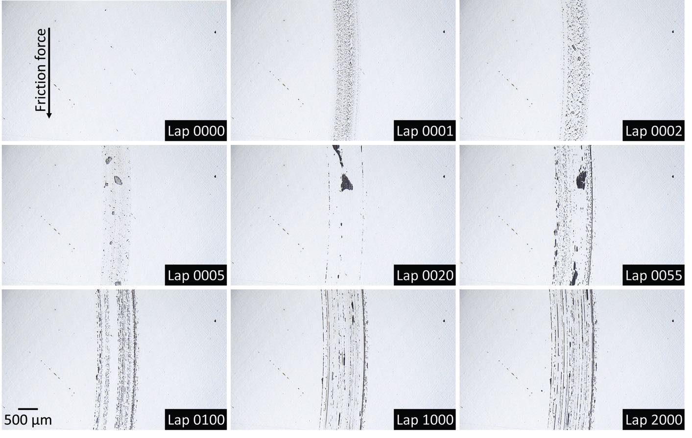
Figure 9. In-situ optical micrographs of a disc wear track for a PTFE/AISI 304 sliding test with mild wear (at 50% relative humidity).
Figure 10 shows the real-time specific wear rate and coefficient of friction for both severe and mild wear cases.5 In the case of severe wear the wear rate is high throughout the test, while for mild wear the wear rate is initially high, but experiences a sharp severe- to-mild wear transition in the first 100 sliding cycles and eventually plateaus at a near ultralow wear rate of 2×10⁻⁶ mm3/Nm.
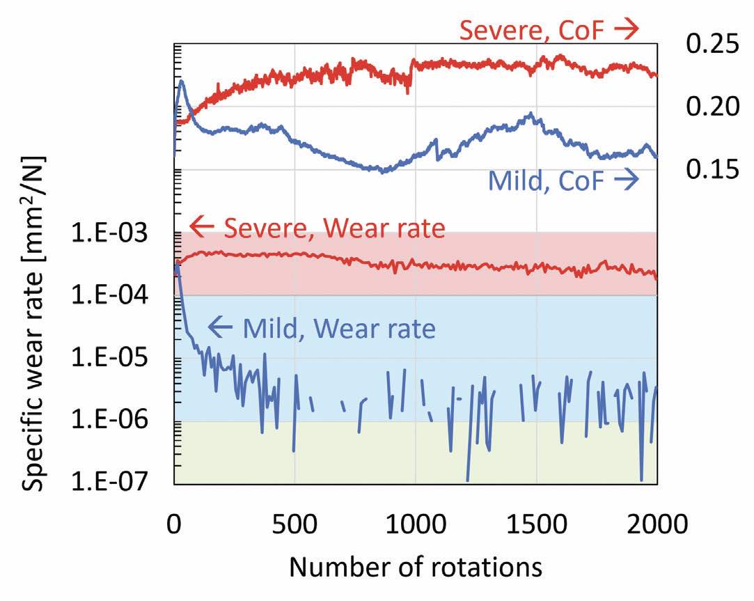
Figure 10. Graph of real-time specific wear rate and coefficient of friction against number of rotations for severe (at 5% relative humidity) and mild (at 50% relative humidity) PTFE/AISI 304 sliding cases. Note that the discontinuity in the real-time specific wear rate for the mild wear case is due to the negative wear rate, implying the build-up of materials, which cannot be presented in a log scale graph.5
To summarize, all PTFE/AISI 304 sliding tests begin with a severe wear phase, characterized by constant transfer of PTFE to the disc to form transfer lumps. Poor adhesion between the transfer lumps and the disc leads to migration and merging of PTFE transfer lumps, which eventually are discharged as wear debris. Under humid air condition, a tribofilm is sometimes formed on the pin through transfer of iron from the disc. This layer protects PTFE from wearing and being transferred to the disc and triggers a severe-to-mild wear transition. The transition usually happens within the first 100 sliding cycles.
To trigger a severe-to-mild wear transition, a uniform tribofilm needs to be formed as early as possible before too many PTFE transfer lumps cover the disc surface as this would prevent the transfer of iron to the disc surface. However, the tribofilm is not initiated and formed immediately as it takes time for the shearing of PTFE to cause enough chain scission to make PTFE reactive to iron. It is hypothesized that the oxides that are naturally present on stainless steel surfaces play an important role in either delaying the transfer of PTFE to the disc by reducing the adhesion, or by accelerating the tribo-chemical reactions of PTFE. Since it is rather difficult to control the amount of naturally formed oxides on the stainless steel surface prior to sliding tests, it is not surprising if some discs have more oxide than others which thus results in the observed poor repeatability displayed previously, in Figure 3.
To verify this idea, a new set of experiments was conducted in which additional oxides were introduced to the disc surface by heating the samples to 100 C for 60 minutes prior to performing the sliding tests. EDS analysis shows a 30% increase of oxygen elements on the surface compared to the discs used in the previous experiments. Figure 11 shows the steady-state specific wear rate and coefficient of friction for PTFE pins against these pre-oxidized AISI 304 discs at differ ent levels of humidity.5 These experiments resulted in much better repeatability of friction and wear results; mild wear is observed consistently at 50% and 95% humidity, while severe wear is observed at 5% humidity. This experiment confirms the hypothesis that preformed oxides on the disc help promote the formation of protective tribofilms onto the PTFE and therefore trigger the severe-to-mild wear transition. The observed severe wear in dry air confirms that water is required to obtain mild wear.
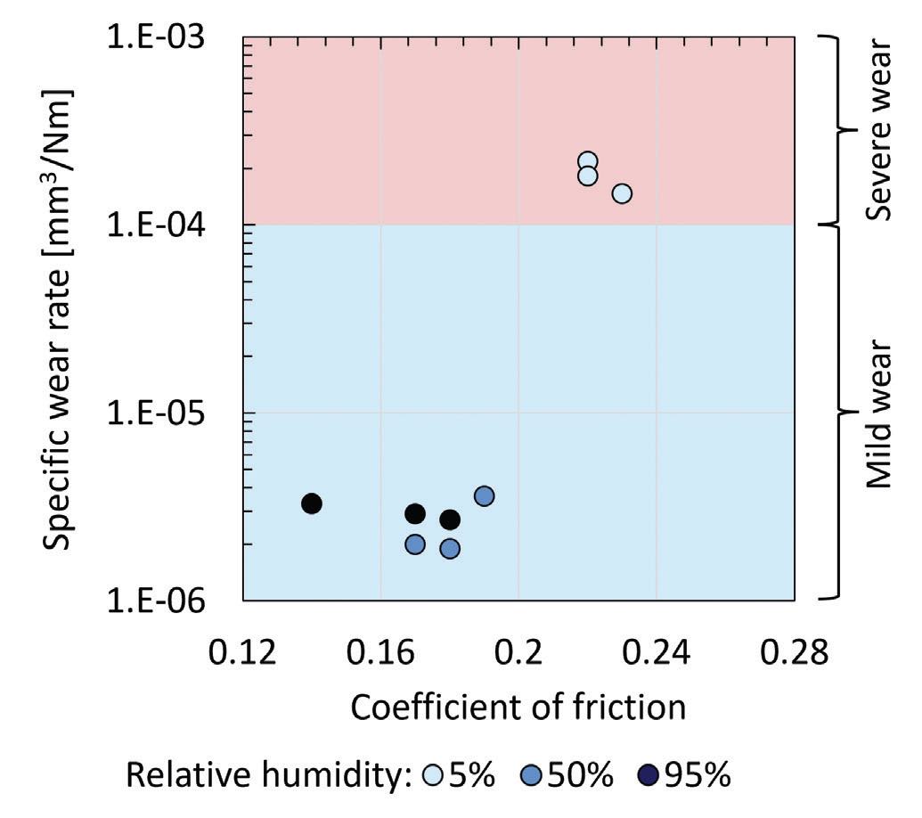
Figure 11. Graph of steady-state specific wear rate of PTFE pin against coefficient of friction for PTFE/AISI 304 sliding at different levels of relative humidity when the discs had been heated at 100 C for 60 minutes prior to the experiment. Data points in the red region have severe wear, while those in the blue region have mild wear.5
Conclusion
Two in-situ tribometry techniques, namely spatiotemporal mapping and optical microscopy, were used to better elucidate the transfer and wear mechanisms involved in sliding a PTFE-stainless steel system. Under the influence of moisture, oxides on the stainless steel surface promote the formation of a tribo-chemical film on the PTFE pin. This prevents the transfer of PTFE to the disc surface and achieves a near ultralow wear rate of 2×10⁻⁶ mm3/Nm without the need for fillers in PTFE. This wear rate is comparable to those of the most wear-resistant high-performance polymers available today, such as PEEK and PI.
Work in progress
The authors are currently working on the real-time quantification of the thickness of the PTFE transfer lumps to understand the transfer mechanisms even further. To do this, a digital holographic microscope (DHM) was installed on the pin-on-disc tribometer.21 The microscope was placed above the disc wear track, opposite the pin so that the 3D height profiles of the lumps can be measured without test interruption. The conditions for the sliding tests were the same as that of the in-situ optical microscopy test described previously except all tests were conducted at 5% humidity to obtain PTFE transfer lumps, which are only generated during a severe wear case. Since PTFE transfer lumps are transparent, their thickness can be computed from the refractive index of the lumps and the phase shift experienced by the DHM laser. An example of DHM height profiles obtained from these experiments is shown in Figure 12.
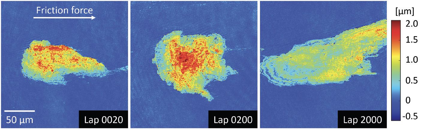
Figure 12. In-situ DHM height profiles of PTFE transfer lumps on an AISI 304 disc.
To validate the results, the thickness measured by DHM is compared with post-test measurements using a laser confocal scanning microscope. It is found that DHM measurement deviates from the measurement of the confocal microscope by up to 40%, which is caused by the change in the refractive index of the transfer lumps during repeated sliding cycles. This finding is important, as it is a common practice in polymer tribology to assume a constant refractive index when measuring polymer transfer films. These results illustrate that extra caution is necessary when such an assumption is made. The authors are currently working on developing a model that describes the refractive index of transfer lumps that enables accurate real-time characterization of the PTFE film thickness.
Acknowledgment
The authors would like to thank the Society of Tribologists and Lubrication Engineers (STLE) for supporting this research through the Elmer E. Klaus Fellowship. The authors are grateful to the Engineering and Physical Sciences Research Council, United Kingdom (EPSRC) for funding this research. Special thanks also go to the awesome collaborators who made this research possible: STLE member Dr. Lucas Amspacher and Dr. Jennifer Vail (formerly) from DuPont de Nemours Inc., U.S., for their support in polymer expertise; STLE member Prof. Kanao Fukuda from Malaysia-Japan International Institute of Technology (MJIIT), Malaysia, for his support in spatiotemporal mapping; Dr. Sergey Shevchik, Prof. Patrik Hoffmann, Dr. Kilian Wasmer (formerly) and STLE member Dr. Pushkar Deshpande (formerly) from the Swiss Federal Laboratories for Materials Science and Technology (EMPA), Switzerland, and Dr. Tristan Colomb and Dr. Yves Emery from Lyncée Tec SA, Switzerland, for their support in in-situ digital holographic microscopy; and Dr. Renato Pero and Dr. Nicholas Randall from Alemnis AG, Switzerland, for their support in in-situ scanning electron microscopy.
REFERENCES
1. Friedrich, K. Friction and wear of polymer composites. vol. 1 (Elsevier, 1986).
2. Batchelor, A. W. & Stachowiak, G. W. Wear of non-metallic materials. in Engineering Tribology 679 (Elsevier, 2014). doi:10.1016/B978-0-12- 397047-3.00016-3.
3. Hutchings, I. Tribology: friction and wear of engineering materials. (Edward Arnold, 1992).
4. Myshkin, N. K., Pesetskii, S. S. & Grigoriev, A. Y. Polymer tribology: current state and applications. Tribol. Ind. 37, 284-290 (2015).
5. Yap, K. K., Fukuda, K., Vail, J. R., Wong, J. & Masen, M. A. Spatiotemporal mapping for in-situ and real-time tribological analysis in polymer-metal contacts. Tribol. Int. 171, 107533 (2022).
6. Blanchet, T. A. & Kennedy, F. E. Sliding wear mechanism of polytetrafluoroethylene (PTFE) and PTFE composites. Wear 153, 229-243 (1992).
7. Burris, D. L., Boesl, B., Bourne, G. R. & Sawyer, W. G. Polymeric nanocomposites for tribological applications. Macromol. Mater. Eng. 292, 387-402 (2007).
8. Alam, K. I., Garodia, A., Bragaw, P. & Burris, D. L. Independently tuning surface and subsurface reinforcement to optimize PTFE wear. Wear 510-511, 204516 (2022).
9. Harris, K. L. et al. PTFE tribology and the role of mechanochemistry in the development of protective surface films. Macromolecules 48, 3739-3745 (2015).
10. Chen, W. X. et al. Tribological behavior of carbon-nanotube-filled PTFE composites. Tribol. Lett. 15, 275-278 (2003).
11. Van Meter, K. E., Junk, C. P., Campbell, K. L., Babuska, T. F. & Krick, B. A. Ultralow wear self-mated PTFE composites. Macromolecules (2021) doi:10.1021/acs.macromol.1c02581.
12. Campbell, K. L. et al. Ultralow wear PTFE-based polymer composites - the role of water and tribochemistry. Macromolecules 52, 5268-5277 (2019).
13. Fukuda, K. Friction force measurement methods and its measuring devices. (1992).
14. Belin, M. & Martin, J. M. Triboscopy, a new approach to surface degradations of thin films. Wear 156, 151-160 (1992).
15. Loubet, J. L., Belin, M., Durand, R. & Pascal, H. Triboscopic description of local wear phenomena under an AFM tip. Thin Solid Films 253, 194–198 (1994).
16. Fukuda, K. Combinational analysis of multi-data obtained in a repeated sliding system. Wear 264, 499-504 (2008).
17. dos Santos, M. B., Costa, H. L. & De Mello, J. D. B. B. Potentiality of triboscopy to monitor friction and wear. Wear 332–333, 1134-1144 (2015).
18. De Oliveira, M. M., Costa, H. L., Silva, W. M. & De Mello, J. D. B. B. Effect of iron oxide debris on the reciprocating sliding wear of tool steels. Wear 426-427, 1065–1075 (2019).
19. Lorenz, L., Makowski, S., Weihnacht, V., Krause, M. & Lasagni, A. F. Advantages of using triboscopic imaging: case studies on carbon coatings in non-lubricated friction conditions. Materials (Basel). 15, 4317 (2022).
20. Krick, B. A., Hahn, D. W. & Sawyer, W. G. Plasmonic diagnostics for tribology: In situ observations using surface plasmon resonance in combination with surface-enhanced Raman spectroscopy. Tribol. Lett. 49, 95-102 (2013).
21. Meylan, B., Ciani, D., Zhang, B., Cuche, E. & Wasmer, K. A new ball-on-disk vacuum tribometer with in situ measurement of the wear track by digital holographic microscopy. Surf. Topogr. Metrol. Prop. 5, 044004 (2017).