Meet the Presenter
This article is based on a webinar presented by STLE member Dr. Harpal Singh and Auburn University on April 6, 2021, titled Wind Turbine Tribology. The webinar series, titled The Beard Tribology Webinar Series, is named after the late Ralph Beard, who pioneered the study of tribology at Auburn. For more information on the webinar series, visit www.eng.auburn.edu/programs/tribology/beard-tribology-webinar.html.
Dr. Harpal Singh is a former principal scientist, tribology & materials, at Sentient Science where he engaged in wind turbine and aerospace-related mechanical and materials science research involving tribology, materials characterization and failure analysis. He is now senior staff, Tribology and Materials Failure Analysis, for Rivian Automotive.
Singh has more than nine years of experience in the field of tribology and metallic materials. He holds a patent, several peer-reviewed publications and two best paper awards from STLE in the field of solid lubricants. He earned his doctorate in mechanical engineering from the University of Akron, Ohio. His research was focused on the mechanical, material and tribological properties of materials and coatings used in wind, automotive and aerospace applications. His expertise includes materials characterization, tribological testing, coatings and failure analysis.
You can reach Singh at harpalsr8@gmail.com.

Harpal Singh
KEY CONCEPTS
•
Challenges to wind turbine components, including bearings and gears, can significantly impact reliability.
•
Bearings at different locations within the wind turbine require various tribological solutions.
•
Causes of failures include false brinelling/fretting corrosion, micropitting, dents/indentations, scuffing/smearing, white etching cracks and butterfly wing formations.
•
Methods to extend reliability of tribological components depend on the cause of failure.
Growth of operating wind turbines has increased worldwide. Their optimized maintenance is crucial as it impacts the cost of energy. Component failures in wind turbines are a major cause of downtime in energy production for unplanned maintenance, repairs and replacements.
1
This article is based on a webinar, titled Wind Turbine Tribology, and presented by STLE member Dr. Harpal Singh—former principal scientist, tribology & materials, at Sentient Science and now senior staff, Tribology and Materials Failure Analysis, for Rivian Automotive. See Meet the Presenter for more information.
Tribological components such as bearings and gears do not fail as often as electronic components in a wind turbine but are the costliest to maintain throughout a turbine’s design life. Figure 1 shows a simplified image of wind turbine components. In a previous TLT article, it was discussed that wind patterns across the globe vary over the years and can be unpredictable at times, with this variability in wind leading to fluctuating loads on wind turbine components. A typical wind turbine consists of more than a dozen bearings that are expected to work simultaneously and continuously for many years. As a result, wind turbine bearings and gearboxes are often susceptible to failure well before their designed service lives.
1
 Figure 1. Wind turbine components.3
Bearings are machine elements that are designed for friction reduction, transfer of load and guidance of moving parts. Bearing failures in wind turbines are a major cause of downtime in energy production for unplanned maintenance, repairs and replacements. Bearing failures are a primary cost and result in higher operations and maintenance (O&M) costs for the energy operator and in higher utility bills for the customer. The National Renewable Energy Laboratory’s (NREL) Gearbox Reliability Database (GRD) shows that 76% of gearboxes fail due to bearings, while 17% fail due to gear failures.
2 This shows the importance of reliable bearings and gearboxes for wind turbine operations to the economy and society.
1
The gearbox in a wind turbine consists of several bearings that translate the wind energy from the spinning blades into electrical energy
(see Figure 1). In the 21st Century, bearings are one of the most critical mechanical/tribological components used in a wide range of applications, including aerospace, automotive, energy, medical devices, sporting equipment and so on.
1
Wind turbines include different types of bearings depending on their load handling capabilities
(see Table 1) and require different lubrication practices for their operation. Pitch bearings, main shaft bearings, generator bearings and yaw bearings require grease lubrication whereas gearbox calls for an oil lubricant. Bearings used in yaw drive orient the rotor perpendicular to the wind direction, and pitch system bearings support pitching system to control power and rotor speed. Bearings on a rotor shaft support the main shaft and rotor blades; bearings in drivetrain support gearbox and generator shafts including associated components:
•
Yaw drive bearings (grease)
•
Pitch bearing (grease)
•
Main shaft bearing (grease)
•
Gearbox bearings, if any (oil)
•
Generator bearings (grease).
3
Bearings and gearboxes in wind turbines are designed and certified to last for at least 20 years; however, higher failures are experienced due to challenging operating conditions. As a result, many bearing OEMs are taking special interest in bearings used in wind turbine applications with the desire to design stronger, tougher and more reliable bearings.
1
The wind industry recognizes the importance of lubricants as critical components contributing to maintenance cost and the life and reliability of wind turbines. Thus, it is important to formulate oils and greases with optimal base stocks and customized additive packages that meet or exceed specific requirements of an application.
Failure modes in tribological components
Common failures
(see Table 2) in wind turbine bearings occur due to
false brinelling/fretting corrosion. These are most common on pitch and yaw bearings and occur under repetitive small motions, which are essentially caused under small oscillations with or without corrosion. Lubricants squeeze out resulting in removal of oxide films, which then leads to adhesive wear in the form of false brinelling. The removal of this oxidation layer creates metal-to-metal contact and increases the oxidation, which results in hematite (iron oxide crystals)—thus, causing fretting corrosion.
Fretting corrosion or brinelling can be prevented by maintaining a lubricant film and preventing adhesion of surface asperities.
Other possible solutions to false brinelling/fretting corrosion are to lubricate contacts with improved grease formulations and antiwear additives or by the use of solid lubricants/coatings and surface treatments. Frequent rotation of bearings prevents rolling element vibration at the same place, and rotation distributes the wear uniformly around the raceway.
Micropitting or surface-initiated fatigue is a major concern in a main shaft bearing that affects reliability in a wind turbine operation. Here micrometer-sized pits form due to asperity shear, plastic deformation of surface asperities. The formation of micrometer- sized pits progressively removes material in contact, which alters the surface profile and eventually creates large stress concentrations. These pits are associated with low lambda regime and high contact pressures. Factors affecting micropitting include surface finish, lubricant, load, temperature, slide-to-roll ratio, speed and material.
There are some possible solutions to micropitting, such as the use of thin and hard coatings (e.g., diamond-like carbon [DLC]) or thick sacrificial coatings (e.g., black oxide), which may aid in controlling surface roughness—large bearings have higher roughness than smaller bearings. Also, the use of specialty additives, such as micro/nanoparticles, may help provide protective and repair effects on metal surfaces. An accurate design and equivalent load sharing during operation will help reduce the risk of micropitting and ensure longevity.
Dents/indentations are foreign abrasive particles or debris generated within the system that can become entrapped between raceways and rolling elements. This concern may cause dents and indentations to mechanical components as debris damage decreases fatigue life. Damage and life reduction is a function of a particle’s size, material (brittle versus ductile) and hardness. Damage severity depends on a dent’s slope and area (dent diameter as a proportion to contact width). Sources of particles include wear particles generated during run-in, contamination during manufacturing and/or maintenance activities. There are some possible solutions such as the use of appropriate oil filters and the use of certain DLC coatings with superior properties on rolling elements that may prevent wear and the generation of debris, and hence, prevent indentations.
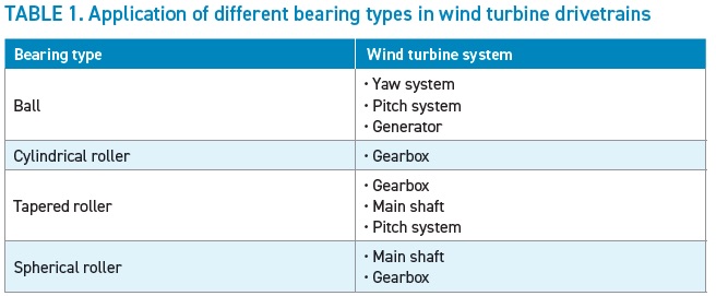
Scuffing/smearing of high-speed shaft
(HSS) bearings is a type of adhesive wear that occurs in two mating surfaces when material transfers from one surface to another under frictional heating
(see Figure 2). Smearing/scuffing occurs under high load and slip condition, that is, sudden changes in the magnitude and/or the direction of a torque load (transient loading). These transient loads can lead to sudden acceleration and deceleration, ultimately causing high slip, which causes the surface to be roughened due to localized melting. There are some possible solutions to scuffing/smearing, such as selecting an optimized lubricant with optimum additive formulations like the use of DLC and black oxide coatings.
 Figure 2. Smearing example on the surface of high-speed shaft bearing and etched cross-section showing microstructure alteration near the surface due to severe heat generation from smearing. Figure courtesy of Sentient Science Corp.
White etching cracks (WECs)/axial cracks
Figure 2. Smearing example on the surface of high-speed shaft bearing and etched cross-section showing microstructure alteration near the surface due to severe heat generation from smearing. Figure courtesy of Sentient Science Corp.
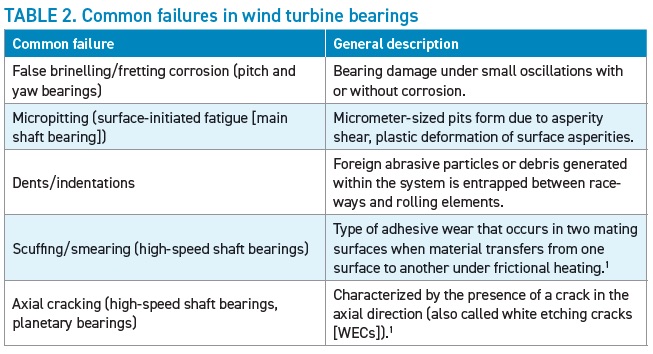
White etching cracks (WECs)/axial cracks in HSS bearings and planetary bearings can jeopardize reliability. These issues are characterized by the presence of a crack in the axial direction
(see Figure 3). WECs are characterized as cracks that are surrounded by local areas of nanograined microstructural alterations.
 Figure 3. High-speed stage bearing showing (a) surface axial crack and (b) cross-sectional view of the axial crack.4
When a bearing containing axial cracks is sectioned and the subsurface is etched, in this case with Nital (i.e., nitric acid and ethanol), the nanograined alterations resist the etchant and appear white, hence the name.
Axial cracks also occur from butterfly wing formations around non-metallic inclusions as observed on planet stage bearing (PS BRG) and low-speed intermediate stage bearing (LSIS BRG)
(see Figure 4). It is frequently observed that cracks accompanied by microstructural alterations in the vicinity of inclusions cause premature bearing failures. Inclusions serve as crack nuclei and can initiate microstructural alterations commonly referred to as butterfly wings.
4 It is observed during extensive characterization that:
•
Dual phase inclusions (MnS + oxide) have higher tendency for crack initiation than MnS inclusion within the Hertzian stress zone—MnS is manganese suplhide inclusions.
•
Cracks are generated from cumulative stress risers located at defects such as inclusions, pores originating from processing or microscopic cracks associated with martensite transformation products (DER).
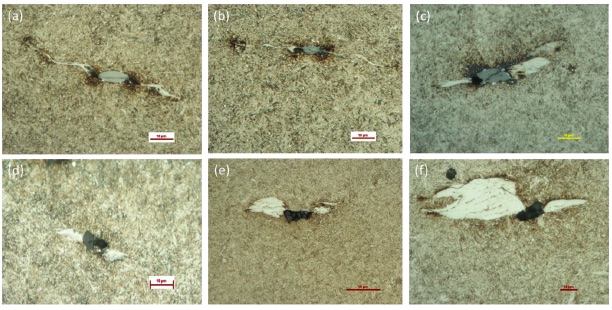 Figure 4. Butterfly wing formations observed in axially cross-sectioned planet and low speed bearings.5
Axial cracking can occur with or without the presence of non-metallic inclusions and independently of material and bearing type. However, some materials are considered more resistant to WEC. There are tribological drivers for WEC formation, which are being contested, and several theories are published associating WEC formation with hydrogen ingress in the microstructure, stray currents, transient loads, non-metallic inclusions and frictional heat energy
(see Figure 5a). For another observation of WEC initiation and propagation at the subsurface, see Figure 5b.
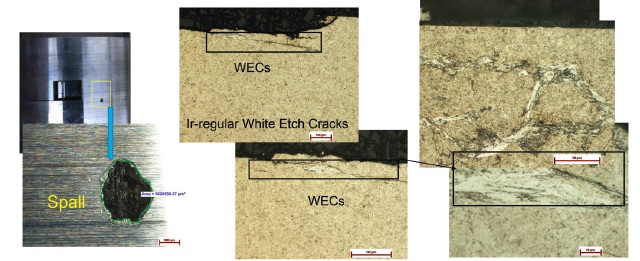
Figure 5a. Failure modes in tribological components. Ir-regular white etching cracks (Ir-WECs) in high-speed stage bearings.4
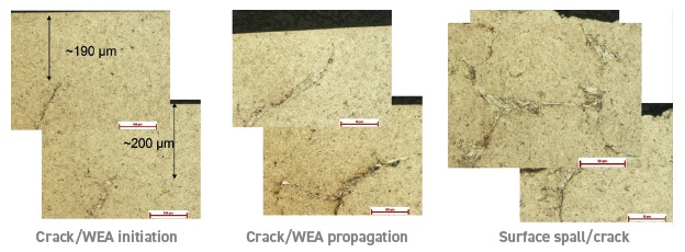
Figure 5b. Failure modes in tribological components. Ir-WECs in high-speed stage bearings.5
Manufacturers are diligently working on improving methods focused on extending reliability of bearings for wind turbine applications. Some of the possible solutions to extend bearing life include the use of black oxide conversion coating, superior heat treatments (case hardened appears to have high resistance) and the use of improved materials with new compositions in the manufacturing process.
Surface treatments for life extension and improved performance
Surface treatments for life extension and improved performance include the use of
micro/nanoparticle additives (see Figure 6), which are broadly divided into two types:
•
Surface treatment
-
In situ tribofilm formation through tribochemical interactions
- Passivates the rough surface in the contact zone
- Modifies contact surface and forms a nanocoating that bonds with metal surfaces
•
Nanoparticle dispersion in a lubricant oil
- Infiltrate small gaps between rough surfaces
- Surface enhancement by surface smoothening effect.
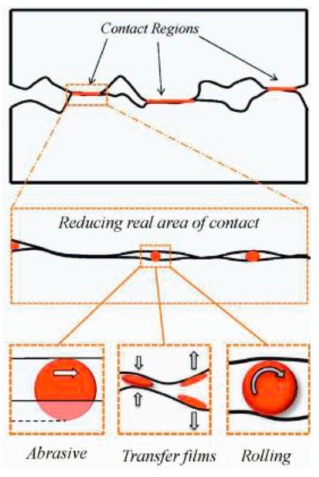 Figure 6. Schematic showing various roles of nanoparticles in contact’s tribology.6
Black oxide
Figure 6. Schematic showing various roles of nanoparticles in contact’s tribology.6
Black oxide is another option of surface treatment for life extension and improved performance:
•
Formed by chemical reactions of steel surfaces when immersed in alkaline aqueous salt solutions
•
Reactions produce oxide layers consisting of FeO, Fe
2O
3 and Fe
3O
4
•
Dark black surface layer of approximately 1-3 μm in thickness
•
Designed to improve running-in behavior, reduce asperity contact, and prevent smearing and micropitting and WECs by reducing hydrogen permeation.
DLC coatings are another surface treatment for life extension and improved performance.
•
DLC coatings have a desirable tribological performance.
•
There are a wide variety of DLCs doped with hydrogen, metals, nitrogen and carbides.
•
Properties of DLCs vary depending upon composition, deposition system, hydrogenated, metal doped and more.
•
Metal-doped DLCs have high mechanical hardness, excellent wear resistance and load bearing capacity.
•
Performance of DLC coatings is affected by temperature and environment.
•
Lubricant oils containing additives can have both positive and adverse effects on DLC coatings.
DLC coatings are used in numerous applications for wear resistant purposes due to their desirable tribological performance. DLC has been modified over the years to possess ultra-low friction and high wear resistance. DLC coatings can be doped or alloyed to increase their functionality. The properties (hardness, toughness, thermal stability) of DLC coatings are further increased by using novel coating architectures that consist of nanocrystalline precipitates and nanosized multilayers. Hydrogen-free DLC coatings deposited from solid carbon targets can be extremely hard, while hydrogenated DLCs are usually much softer. Precursor hydrocarbon gases such as methane and acetylene are typically used in the deposition of DLC that contain large amounts of hydrogen. Hard DLC have been shown to be very successful at mitigating many wear issues encountered by bearings and gears operation in boundary lubrication, including micropitting. Most of the studies reported on exploring the use of DLC to mitigate micropitting prevention were carried out with hard DLC coatings.
7
Rolling element bearings operating in wind turbine gearboxes employ coatings that are either applied only to rolling elements (hard DLC) or both rolling elements and raceways (i.e., black oxide).
Below are several case studies that describe DLCs.
Case 1: Performance of highly hydrogenated DLCs
The material pairs tested in a recent study
7 were designed to be consistent with the application of coatings on wind turbine bearing components. The performance of the H-DLC coatings was examined by testing four material pairs: uncoated roller on uncoated rings, H-DLC coated roller on uncoated rings, uncoated roller on H-DLC coated rings and H-DLC coated roller on H-DLC coated rings.
7
•
Highly hydrogenated DLC (H-DLC), ~1 mm thick, is deposited by magnetron sputtering, with ~0.1 mm Cr adhesion layer.
•
Carbon from the H-DLC (and also possibly from the synthetic base oil) forms an amorphous carbon tribofilm containing iron oxide (Fe
3O
4) on uncoated steel surfaces during testing.
•
Micropitting rig (MPR) tests conducted on uncoated, steel on steel, material pair failed after 32 million cycles due to excessive surface damage. Remarkable reductions in surface damage of the roller were observed when one or both elements were coated with H-DLC. Traction coefficients were ~ 0.04 and remained relatively constant throughout the testing for the three cases where at least one of the contacting surfaces was coated. Furthermore, no failures were observed, and the tests were suspended after ~ 100 million cycles. Roller wear was quantified according to a change in width of the roller wear track
(see Figure 7). A clear trend is seen between change in track width and the amount of coating available to participate in the tribological contact. For example, the least amount of coating passing through the contact was for the H-DLC-coated roller on uncoated ring pair, while the largest amount of coating passing through the contact was for the H-DLC-coated roller on H-DLC-coated ring pair, considering the difference in coated sample surface area. This trend suggests that the wear occurring on the roller depended upon the amount of H-DLC present in the contacts. H-DLC offers a promising surface treatment to mitigate fatigue-initiated micropitting wear on surfaces of components operating in low
λ ratio rolling and rolling/sliding contacts. The improved performance was attributed to the formation of an amorphous carbon tribofilm containing iron oxide on uncoated steel surfaces during testing which was confirmed by the Raman spectrum of the tribofilm. The H-DLC coating has a low friction coefficient that may delay the onset of micropitting and increase fatigue life through a reduction in shear stresses. The low hardness and modulus of the H-DLC resist fracture and delamination of the coating under high contact stress cycles and high slide/roll ratios.
8
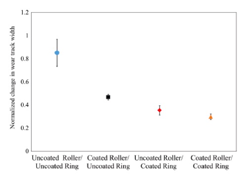 Figure 7. Change in roller track width before and after testing, indicating the amount of wear that occurs on the roller sample.7
The study was performed on an MPR. The MPR is a computer-controlled tribometer with three rings on a roller. A 12 mm diameter roller is mounted in the center and in contact with three rings of 54 mm diameter at an angle of 120 degrees. Figure 8 shows the MPR test chamber. A thermo couple was installed to measure the contact temperature and an external cooler was connected to control the temperature of the oil inside the test chamber. A load was applied to the top ring (0 degree position) by means of motorized ball screw, and vibration was measured with a piezoelectric accelerometer. The rig has a capability to control entrainment speed (0-4 m/s), slide-to-roll ratio (0%-200%), temperature (25-135 C) and load (0-1250 N).
8
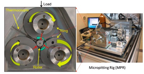 Figure 8. Micropitting rig (MPR).7
Case 2: Metal-doped DLCs with polyaphaolefin and fully formulated gear oils
Figure 8. Micropitting rig (MPR).7
Case 2: Metal-doped DLCs with polyaphaolefin and fully formulated gear oils
In this study, uncoated gear steel, Ti-DLC coated and W-DLC coated gear steel were tested in a rolling/sliding contact on MPR. Two lubricants—PAO4 synthetic base stock oil and a fully formulated (FF) gear oil containing S-P additives—were used to investigate the tribological performance of the coatings. The purpose of this study was to evaluate the fatigue performance and explore the lubricant interaction mechanism with the metal-doped coatings under sliding/rolling contact
(see Figures 9a and b). Rollers and rings were made of 16MnCr gear steel and heat treated to hardness values of 680 HV and 780HV, respectively. The average surface roughness measured on the uncoated roller and ring was about Ra = 0.25 and 0.3, respectively.
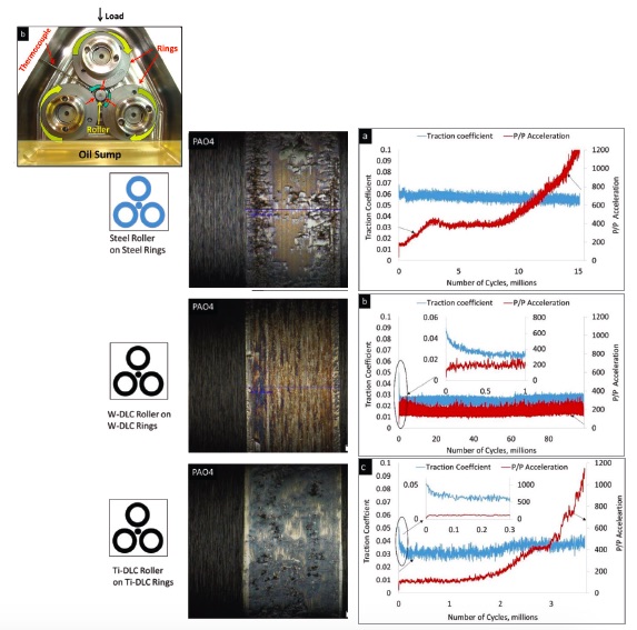 Figure 9a. Performance of metal-doped DLCs with FF gear oil.8
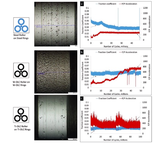
Figure 9b. Performance of metal-doped DLCs with FF gear oil.8
Three materials pairs were studied in PAO4 (polyalphaolefin, PAO).
•
Steel on steel
•
W-DLC on W-DLC (W-DLC is Tungsten-doped DLC)
•
Ti-DLC on Ti-DLC (Ti-DLC is Titanium-doped DLC).
The steel-on-steel pair with the PAO4 lubricant lasted 15 million cycles. W-DLC coating in combination with PAO4 lasted 100 million cycles without significant damage. The Ti-DLC and PAO4 pair lasted only about 4 million cycles.
Materials pairs were studied in FF gear oil containing extreme pressure (EP) additives
(see Figures 9a and b).
•
Steel on steel
•
W-DLC on W-DLC
•
Ti-DLC on Ti-DLC.
The Ti-DLC and PAO4 pair lasted only about 4 million cycles while Ti-DLC with FF gear oil was suspended after reaching 100 million cycles. In both cases, the traction coefficients remained steady throughout the tests. The FF gear oil and steel combination was terminated around 50 million cycles due to a significant amount of wear measured on the roller surface.
Failure mechanisms for all the material pairs differ from one another. Steel on steel plus PAO4 combination failed due to excessive surface damage on the surface of the roller, which exceeded the vibration cut off limit. The surface damage on the roller appears to have initiated with micropits, evolved into macropits, that coalesced and formed the continuous surface damage in the wear track. Different failure mechanisms were observed when metal-doped DLC coatings were used with PAO4 and FF gear oil. The results obtained show that W-DLC did not show significant surface damage with PAO4 base oil while severe pitting was observed on the Ti-DLC roller. This suggests that the coating properties have a direct influence on the fatigue performance under sliding and rolling contact conditions. Optical analysis on the counterface of W-DLC showed polishing effect whereas the Ti-DLC counterface showed coating delamination. The multilayer W-DLC coating containing alternating Tungsten and carbon rich layers appears to be resistant to high shear stress cycles. Hard W-DLC coatings applied to rolling element bearings functioned very well in mitigating micropitting, scuffing and fatigue life reduction from debris damage.
In contrast to the base oil performance, Ti-DLC outperformed W-DLC in FF gear oil, and the test was terminated after 100 million cycles. Optical analysis revealed that the additives in the oil act synergistically in forming a tribofilm on the Ti-DLC surface. W-DLC roller surface also showed the formation of tribofilm on the surface, but the additive interaction was not as significant to reduce wear and increase the fatigue life.
Hydrogen plays a critical role in the wetting behavior of DLC coatings. The hydrogen carbon combination produces a nonpolar, inert surface having a low energy that causes poor wettability and results in no additive interaction on the coated surface. Poor wettability is more of an issue when the carbon network is highly hydrogenated.
Metal dopants in the coatings also have a significant contribution on the formation of tribofilms. It is reported that DLC coatings with metals can lead to high surface energies that promotes interactions between the coatings and the lubricant.
9 Tungsten has lower reactivity with the lubricant additives that takes more running in time to form tribofilms.
9
These results show that the effectiveness of additives depends on the nature of the chemical interaction between the coating and steel. The differences in the coating + additive interaction can be attributed to several factors, including metal and nonmetal doping, hydrogen content and lubricant formulation. The type of chemical species of lubricant additives may react differently with coating composition. It is important to consider the synergistic effect of coating and oils before selecting for a wind turbine application.
Summary
Wind is the fastest growing renewable energy source. It is cost competitive with other non-renewable resources due to technological advancements. However, bearings and gears reliability issues limit desired performance and operating life.
There are a wide variety of surface treatments in the market, i.e., types of coating/surface treatment/additive package, that would be most beneficial to an operator’s wind farm location depending on the operating conditions.
Overall, wind turbines are becoming bigger in size and more powerful leading to new tribological challenges.
REFERENCES
1.
Aikin, A. (2020), “Bearing and gearbox failures: Challenge to wind turbines,” TLT,
76 (8), pp. 38-44. Available
here.
2.
NREL Gearbox Reliability Database. Available
here.
3.
Andrew, J. M. (2019), “Fundamentals of wind turbines,” TLT,
75 (8), pp. 32-40. Available
here.
4.
Singh, H., Pulikollu, R. V., Hawkins, W. and Smith, G. (2017), “Investigation of microstructural alterations in low-and high-speed intermediate-stage wind turbine gearbox bearings,”
Tribology Letters, 65 (3), pp. 1-13.
5.
Singh, H., Pulikollu, R. V. and Smith, G. (2017), “Wind turbine gearbox bearing material analysis to study crack nucleation, propagation and damage mechanisms.” STLE Annual Meeting & Exhibition: Atlanta.
6.
Ghaednia, H. and Jackson, R. L. (2015), “The role of nanoparticles in lubricants; performing lubricated and dry friction tests,” TLT,
71 (7), pp. 20-24.
7.
Singh, H., Ramirez, G., Eryilmaz, O., Greco, A., Doll, G. and Erdemir, A. (2016), “Fatigue resistant carbon coatings for rolling/sliding contacts,”
Tribology International, 98, pp. 172-178.
8.
Singh, H. (2015),
An Investigation of Material Properties and Tribological Performance of Magnetron Sputtered Thin Film Coatings. Diss. University of Akron.
9.
Al Mahmud, K. A. H., Kalam, M. A., Masjuki, H. H., Mobarak, H. M. and Zulkifli, N. W. M. (2015), “An updated overview of diamond-like carbon coating in tribology,”
Critical reviews in solid state and materials sciences, 40 (2), pp. 90-118.