KEY CONCEPTS
•
Measuring and controlling heat generation is especially important for high-performance bearings.
•
The ability to accurately forecast torque and power loss during the design phase of the equipment is very important for OEMs.
•
Many traditional test methods pose limitations in terms of cost, complexity and accuracy.
•
Today’s simulation/modeling software has the potential to remove limitations in all three areas.
Measuring bearing torque is extremely complex. For example, a single tapered roller bearing could have 15 rollers encased in its rings, representing many different contact points. To calculate torque, all of these contact points need to be taken into account—how they are likely to respond to the loads and speeds of a particular application, whether the material might flex under those points, whether the oil between them is being sheared, etc.
Given all this, it’s logical that the study of bearing power loss encompasses many disciplines, such as fluid mechanics, solid mechanics, thermodynamics and heat transfer
(see Contributors to Torque and Power Loss).
Contributors to torque and power loss
According to Joe Poplawski, president J.V. Poplawski & Associates, friction loss that occurs in rolling element bearings can be attributed to:
•
Rolling element to raceway elastohydrodynamic lubrication (EHL) film thickness and traction
•
Hydrodynamic pumping of fluid through the EHL contact
•
Sliding velocity and stress distribution within the contacts
•
Hysteretic
A loss due to elastic working of the material in contact
•
Cage to pilot surface contact
•
Rolling element to cage pocket contact
•
Churning (drag) loss from the lubrication media
•
Oil inertia in transporting the lubricant through the bearing.
REFERENCE
A.
The lagging of an effect behind its cause.
The oil viscosity or resistance to flow can change in unexpected ways as the application pressure, temperature and shear rate in the contact points increase to extreme levels. The fact that oil chemistry has evolved significantly in the last decade further complicates things—predicting bearing efficiency requires understanding the nature of the exact liquid, oil or grease in each application.
STLE member Joe Poplawski, president of J.V. Poplawski & Associates, explains, “Rolling element bearing torque is the resistance to rotational operation of the bearing. This resistance manifests itself as component power loss, heat generation and operating temperature. The origin is friction at loaded sliding surfaces in the bearing.”
STLE Life Member Lavern D. Wedeven, president of Wedeven Associates, Inc., stresses the importance of thermal management. “Bearing torque and heat generation are particularly important for high performance bearings requiring axial and radial stiffness over large ranges of speeds and loads. These applications use angular contact ball bearings (ACBBs) where the interface kinematic motions of the ball/raceway contribute significantly to bearing torque and heat generation. Heat generation at the interface, operating at a contact angle, is derived from interface motion (or slip). Some of that motion is manifested in frictional heat rather than its impact on ring rotational torque. When both ball spin and slip contribute to heat generation at the interface, thermal management functional requirements demand particular attention to heat dissipation and cooling,” he says.
Increasing oil flow, if it is an option, results in additional viscous losses, and, in some cases, diminished returns for thermal management. Increasing oil flow to dissipate heat and thermally manage bearing temperature, while seemingly an obvious solution, is not always the best solution. Flooding the bearing with cooling oil increases the viscous losses within the bearing. “In any case, the prediction of the heat generation for bearings, particularly thrust-loaded ACBBs, is essential. Misjudging loads and motions, and their impact on heat generation and torque, is a major (and potentially catastrophic) risk. This is a highly challenging tribology problem,” Wedeven adds.
Better bearing torque performance: Benefits to OEMs
Improvements in bearing torque performance benefit OEMs in many areas including equipment design and equipment life.
“It is advantageous for the equipment designer and OEM to be able to accurately predict torque and power loss during the design phase of the equipment,” Poplawski says. “This information is relevant to the selection of drive motors, sizing of lubrication and cooling systems and making sure that the bearing operating temperatures do not exceed material capabilities or design clearances in the system. This has a direct impact on the cost and limitations of the machine.”
STLE Life Member Erwin Zaretsky, a consultant with more than 50 years of experience in tribology and retired engineer from the NASA Glenn Research Center, observes that since rolling element bearing materials and lubricants are limited in operating temperature, lower bearing torque manifests in lower bearing operating temperature and lower bearing and lubricant cost. “In my opinion, this will result in longer machinery usage, lower operational costs and longer machinery life and reliability,” he says, adding that today’s rolling element bearing computer codes, used in skilled hands, greatly enhance achieving these design and operating goals.
STLE member Dr. Farrukh Qureshi, Technical Fellow, strategic research, The Lubrizol Corp., sees the advantages of better torque performance for electric vehicles (EVs) in particular. “In order to increase efficiency of the system, bearings will need to be operating more efficiently,” he says. “Since bearing torque is a system response, it would need bearing designs for high efficiency, coupled with lubricants which, in addition to meeting all requirements for EV applications, also deliver higher efficiency to the system. Highly efficient bearing systems will contribute to improved range for EVs.”
R&D manager of product fundamentals and STLE member Dr. William (Bill) M. Hannon of The Timken Co. reminds that the benefits of bearing research have a practical impact on the design of the bearings themselves. “By knowing what parameters drive torque, we are able to better select a lubricant, justify the cost of improvements in surface texture and treat the bearing’s efficiency as being part of a system as opposed to an off-the-shelf commodity.”
Methods for testing/measuring bearing torque performance
Predicting power loss in rolling element bearings can be accomplished in several ways, Poplawski says. For example, T.A. Harris
1 presents closed-form equations that attempt to quantify load-related contributors and lubricant viscous-related contributors. Other methods rely on regression analysis on measured bearing loss to yield an equation that fits the data.
“The accuracy of regression-based models is very good as long as the conditions of interest lie within the data set used to determine the regression coefficients and the bearing geometry is close to that of the test bearing,” he adds.
Classical measurements, still in current use, made use of strain gauge or load cells, which extend from a moment arm. Today non-contacting, inline torque meters are preferred. “Two types of torque measurements are common: ‘torque-to-rotate’ and ‘application testing,’” Hannon explains. “Torque-to-rotate tests are performed at a light load and speeds less than 50 rpm. This allows torque to be proportionated to the bearing setting. Application testing, on the other hand, mimics the higher speed and dynamic loads of a given application.”
These tests allow the quantification of inefficiencies over a given application’s duty cycle. A great example is a wheel bearing test where the direct correlation to power loss improvements required by automotive Corporate Average Fuel Economy (CAFE)
2 laws is apparent.
Qureshi adds, “Several techniques are used to measure bearing torque. Use of an inline torque meter provides accurate torque measurement but is costly. Another technique is to measure the torque moment by using a calibrated torque arm. Motor power input measurement can be used as a rough measure of bearing torque but is not very accurate. These methodologies have served the industry well for the range of load/speed that current bearing applications see in conventional driveline systems. For high-speed bearing applications, from 25,000 rpm to as high as 50,000 rpm, as expected in future applications for EVs, these methodologies may not be adequate.”
Limitations of testing/measuring methods It is one thing to predict the friction of a ball on a plate. It’s another to predict the friction of many rollers that are confined by abutting raceways and a cage. “A ball isolated experiment with precise controls on load and speed,” Hannon observes. “This differs from a bearing and a bearing test. Bearings are dynamic, roller speeds change around the load zone, lubricant splash is abundant, temperatures fluctuate both locally and globally and no two bearings truly have the same surface texture.”
Hannon adds that the gear and seal torque is greater than that of rolling element bearings. “So, bearings tests are typically isolated to a minimum of two bearings mounted to a shaft,” he says. “This permits one to isolate signals and ensure the measured bearing losses are truly due to the bearing. This isolation can be less ideal, and it is especially so in applications where torque is influenced when the neighboring gears splash lubricant to the bearings.”
Qureshi notes that while measurement of bearing torque by using motor input power is probably the easiest method, it is still very inaccurate. “This method can probably be used for looking at the changes in bearing torque to compare them with the impact of operational changes such as speed, load, temperature, oil viscosity, etc.,” he says. “But is not an accurate measure of absolute bearing torque. Using an inline torque meter provides quite accurate bearing torque measurement. This method is expensive due to the cost of the torque meter and instrumentation.”
He continues, “Inline torque measurement is a reliable method for current applications. However, for EV applications where motor input speeds are much higher than conventional applications, inline torque measurement may become technically difficult as well as very expensive. The combination of technical difficulties and the cost of using inline torque measurement for high-speed applications makes this technique less than optimal for high-speed applications.”
Newer testing/measurement methods
While great progress has been made in the prediction of elastohydrodynamic (EHD) film thickness, predicting traction has been elusive, particularly under mixed-EHD film conditions. The good news is that recent developments in bearing contact interface simulation testing and modeling now make it possible to predict heat generation and resistance to motion for bearing torque, Wedeven observes.
According to Hannon, while the fundamentals of torque loss have been well established since the 1960s, advances have been in the subtleties. “Three examples come to mind: first the effects of lubricant starvation on torque; second the rheological measurements and predictions that allow one to accurately model sliding friction; and third the ability to transition from boundary, through mixed and onto full film friction,” he explains.
Hannon continues, “Today’s approach begins by quantifying a lubricant. That involves high pressure and high shear measurements of viscosity and other properties. This is then complemented by studying the friction of a ball on a plate. That test confirms the ability to predict sliding friction, and it gives the lubricant’s limiting shear stress (the only lubricant property we were missing). At the same time, other fundamental tests have been performed, like detailed surface texture measurements and dimensional metrology of a rib angle. These first-principle attributes then feed a model. The model predicts torque. Today, when we finally do measure the bearing’s torque, it is for confirmation of the models. This is a change in methodology; we are now placing the import on fundamental tests as opposed to a system-level bearing test.”
Newer methodologies may include non-contacting methods that would not include inline bearing torque measurement for high-speed bearing applications, with potential use in EVs, Qureshi adds. “These measurement methods are proprietary (to my knowledge) to different developers, and details may not be publicly available. The newer methodologies would certainly be more expensive than the current methods but would obviate the gap of technical challenges faced by inline torque meters in high-speed applications.”
High-end bearing users, such as gas turbine engine OEMs, use physics-based software that contains mathematical models descriptive of bearing behavior, Poplawski explains. The earliest of these was offered in the 1960s by A.B. Jones
3 and is still in use today. The SHABERTH
4 software, developed by SKF through NASA Lewis Research Center funding, was offered in the 1970s and also is still in use. In 2000, the COBRA-AHS
5 software, also developed through NASA Glenn Research Center funding, became available.
Fundamental physics-based disciplines and software modeling
While the traction of the primary bearing raceway interfaces are controlling bearing motion and dynamics, the secondary interfaces associated with the cage contribute to drag. Single contact tribology tests are available to conduct cage/land and cage/RE friction tests.
Wedeven explains that the results of these tests can then be modeled and incorporated into bearing analysis software code.
Poplawski notes that the development of physics-based models requires the knowledge of solid mechanics to quantify the stresses developed within the rolling/sliding contacts and their subsurface regions. Kinematics is required to determine the six-degree of freedom ball motion in the bearing. The behavior of the lubricant within a contact is non-Newtonian and requires a viscoelastic representation for its behavior.
He adds that heat transfer analysis allows the determination of bearing operating temperatures and temperature distributions that result from heat generation and fluid cooling within the component. These temperature distributions result in dimensional change that effects bearing operating fits and clearances.
“These resulting changes in fits and clearances will alter the heat generation, temperature distribution and bearing fit up from that originally derived,” Poplawski says. “Thus, an iterative process is required to establish the final equilibrium state between the bearing model and heat transfer thermal model of the bearing.”
Poplawski goes on to explain that additional heat generation from churning (drag) loss develops as the rotating pieces are traveling through a mixture of lubricant and air. Typical models used are for drag loss for a sphere or cylinder exposed to a free stream velocity. Metallurgy, description of surface topography, numerical methods and finite element analysis (FEA) are additional disciplines used in the development of these physics-based models, which can be quasistatic or time transient.
“Physics-based models have a broader base of application since they are based on ‘first principles’ and are meant to be a digital twin of the bearing being studied,” Poplawski says. “However, physics-based models, such as SHABERTH, fell short of capturing the increase in bearing heat generation when single row (SIR) ball bearings were tested under very high-speed and high-thrust load. Forster
6 presented such data on a 133 mm SIR ball bearing and compared power loss at speeds to 2.6 MDN (million DN, where DN is the bearing bore in mm times the speed in rpm) and thrust loads to 12,000 pounds.”
Poplawski believes that the introduction of FEA into bearing analysis gives bearing engineers the capability of converting bearing power loss into temperature distributions and bearing dimensional change at an accuracy level that surpasses the older classical methods.
“The capabilities of physics-based models built upon first principles to give a ‘digital twin’ of the bearing are useful in determining the magnitude of each contributor to torque for a given bearing geometry and set of operating conditions,” Poplawski says. “Therefore, the designer can now attack the key contributors to reduce torque.”
Tribology-by-Design
Wedeven explains: “Tribology-by-Design (T/D) refers to a theory, a set of test and analysis tools and a methodology. T/D was developed to enhance innovation and to reduce response time and risk associated with the technology readiness level (TRL) approach used for major mechanical system development
(see Technology Readiness Levels (TRLs)).
Technology readiness levels (TRLs)A
Technology readiness levels (TRLs) were developed by NASA in 1974 and formalized in 1989. Their purpose is to evaluate the technology readiness of proposed programs. The following commonly accepted TRL levels, adopted by the EU, closely match the original NASA TRLs.
1.
Basic principles observed
2.
Technology concept formulated
3.
Experimental proof of concept
4.
Technology validated in lab
5.
Technology validated in relevant environment
6.
Technology demonstrated in relevant environment
7.
System prototype demonstration in operational environment
8.
System completed and qualified
9.
Actual system proven in operational environment.
REFERENCE
A.
Click here.
The T/D theory links the motion, stress and temperature (MST) of the interface to the tribology interface materials, mechanisms and manifestations (Tm) during operation. Using surface analysis and component analysis tools, the targeted component interface, represented by MSTTm, is extracted from an operating TRL 8 system component and delivered to an accessible and workable level, TRL 4. This allows tribology interface research and engineering to be conducted on a pseudo-virtual design basis for innovative, rapid and low-risk development.”
Three T/D tools enable tribology engineering design of MST-Tm:
•
Contact simulation testing
•
Single contact modeling (SCM)
•
Bearing interface analysis.
These companion tools provide digital and simulation twins of the operating component to enable tribology designs for low traction and durable component interfaces in a controlled TRL 4 research and development environment targeted to a TRL 8 operating application.”
“A recent major breakthrough that enables the success of T/D is the ability to model traction over a wide range of conditions,” Wedeven continues. “Using advanced thermal and rheological models, along with the extraction of critical information from high-speed simulated contacts, successful traction modeling is achieved for bearing torque and thermal modeling. The thermal and traction models are incorporated into a single contact model (SCM) and validated with single contact simulation testing. T/D is achieved through companion test and analysis tools shown in Figure 1.”
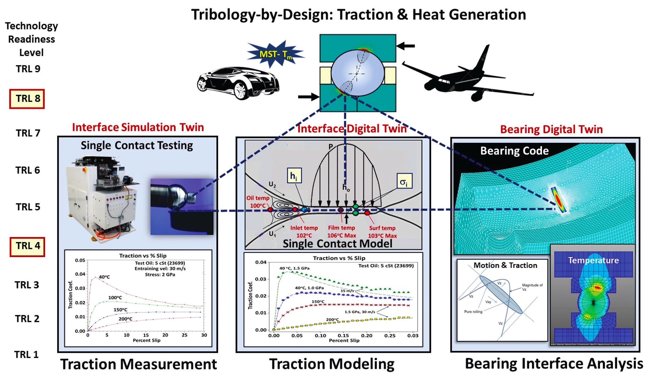 Figure 1. Tribology-by-Design test and analysis tools and technology readiness level methodology roadmap. Figure courtesy of Lavern D. Wedeven.
With this traction modeling capability
(see Figure 2), advanced bearing analysis codes are then used to converge on motions, calculations of heat generation and thermal modeling of a targeted bearing and its operating environment
(see Figure 3). These T/D tools enable evaluation of bearing designs, lubricants, bearing materials, processes, finishing features, thermal management schemes and finally bearing torque and heat generation.
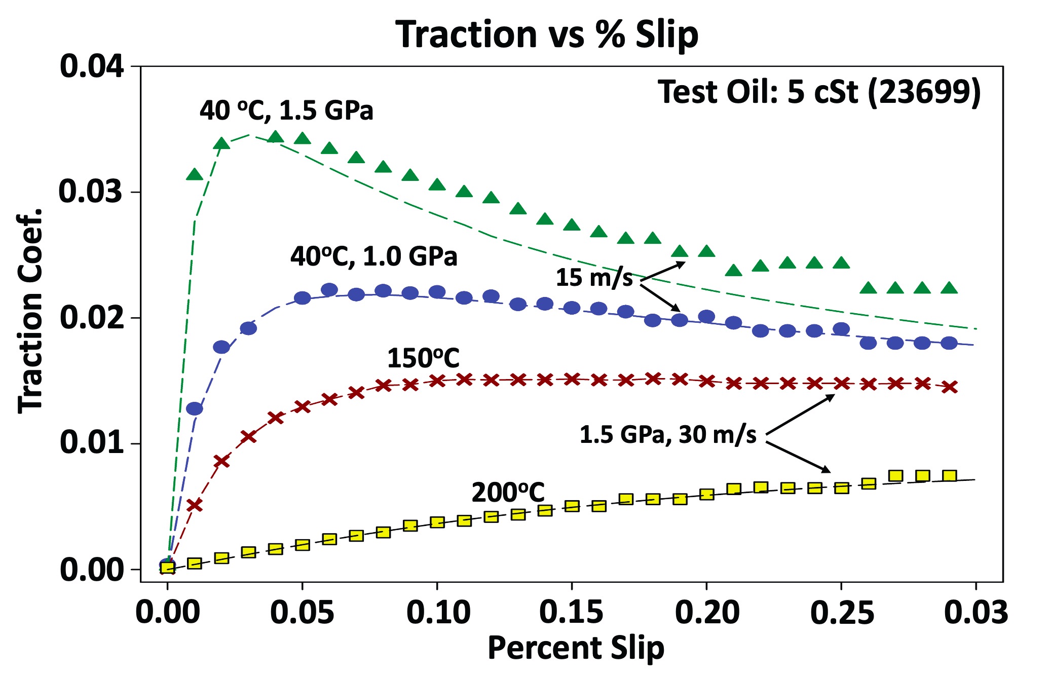 Figure 2. Tribology-by-Design test and analysis tool: traction modeling. Figure courtesy of Lavern D. Wedeven.
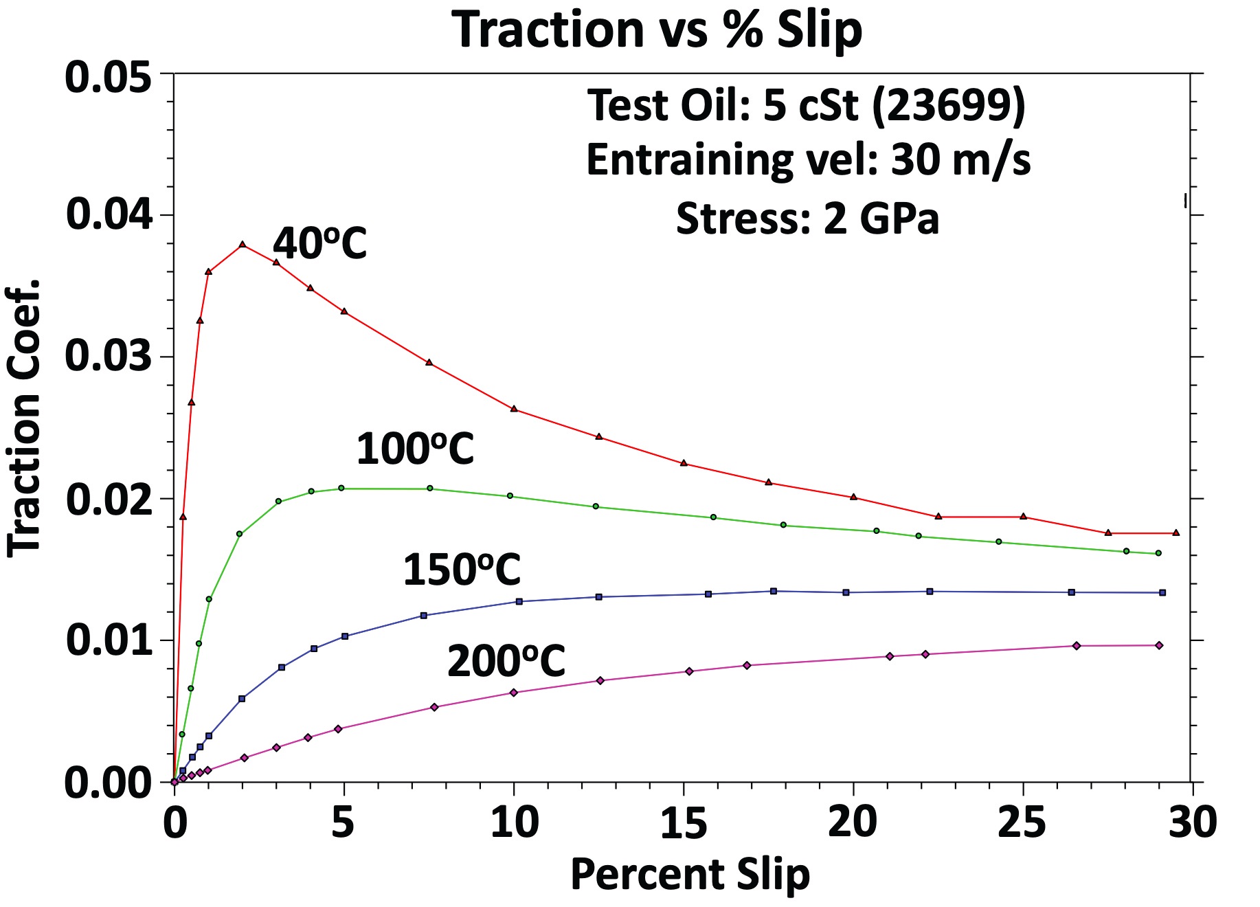
Figure 3. Tribology-by-Design test and analysis tool: traction measurement. Figure courtesy of Lavern D. Wedeven.
“The T/D theory, the set of tests and analysis tools and methodology, provides a means to develop and assure durability (i.e., life and reliability),” Wedeven notes. “With enhanced thermal and kinematic motions within the bearing, high precision calculations can be made of contact interfaces for EHD film thickness and sliding velocities.”
These film thickness, velocity and thermal calculations allow examination of the traditional lambda ratio (h/s) design parameter representing EHD film thickness (h) divided by the combined surface roughness (s). The reduction of lambda ratio below a certain minimum is a necessary but not sufficient condition for surface distress (wear, scuffing and fatigue).
“The motion-driven tribology mechanisms for bearing performance are quite different for high-speed applications than they are for low-speed applications,” Wedeven cautions. “High speeds are usually associated with ample EHD film generation, high temperatures and low traction.”
He adds, “Interface tribology mechanisms associated with local micro-EHD films caused by topographical texture features can play a significant role affecting traction and local film generation. The roughness and texture features under high speed (particularly with high sliding velocity) can actually flatten the topography. Low speeds are usually associated with extremely thin films (h) relative to surface roughness (s). Here, the lambda ratio (h/s) loses its meaning.”
For low h/s performance operation, Wedeven introduces the notion of a T/D performance parameter, h
i/s
i. Instead of film thickness (h), it addresses all the interface hydrodynamic motion-driven mechanisms, including traction (h
i). Instead of surface roughness (s) it addresses all the interface materials and mechanisms associated with the integrity of the bounding surfaces (s
i).
The above advances in traction modeling, single contact simulation testing and single contact modeling are enabling advanced bearing analysis codes to accurately predict bearing torque and temperature. The development and utilization of T/D theory, the set of test/analysis tools and methodology create opportunity to provide innovation and rapid response to bearing technology needs for torque, efficiency, thermal analysis and durability for targeted and critical bearing applications.”
Areas for future research
Hannon believes that there is a need for cohesive models. “For example, we have confidence in the modern rheological models, but since we need rapid computations (be it for design, or understanding a duty cycle), it is still a challenge to ensure the peripherical models make efficient use of the rheological models,” he says. “Improvements also are needed in obtaining rapid and accurate computations of mixed mode friction.”
Poplawski agrees. “One area that needs improvement is the modeling of the flow of the coolant/lubricant through the bearing and estimation of associated drag loss. Computational fluid dynamics (CFD) has brought an FEA-type approach to modeling the flow of fluid through the bearing. This method when applied to flow within and around the moving/spinning bearing elements is computationally intensive with complex boundary conditions. Successful analysis of this type will more accurately define the convective heat transfer coefficients on the surfaces in the bearing and viscous losses due to the media flow,” he concludes.
Acknowledgements
J.V. Poplawski and L.D. Wedeven gratefully acknowledge support from the U.S. Air Force (AFRL), Navy (NAVAIR) and Army (DEVCOM AvMC).
REFERENCES
1.
Harris, T. A. (2001),
Rolling Bearing Analysis, Fourth Edition, John Wiley & Sons, Inc., Chapter 14.
2.
Corporate Average Fuel Economy: U.S. regulations designed to improve average fuel economy in cars and light duty trucks.
3.
Jones, A. B. (1960), “General theory for elastically constrained ball and roller bearings under arbitrary load and speed conditions,”
ASME Trans. J. Basic Eng., Vol. 82.
4.
Crecelius, W. J. and Pirvics, J. (1976), “Computer program operation manual on ‘SHABERTH’ a computer program for the analysis of the steady state and transient thermal performance of shaft-bearing systems,” AFAPL-TR-76-90.
5.
Poplawski, J. V., Rumbarger, J. H. and Peters, S. M. (2002), “Advanced analysis package for high speed multibearing shaft systems: COBRA-AHS,” NASA, USA, Final Report, NASA Contract NAS3-00018, 2002.
6.
Forster, N. H., Svendsen, V. R., Givan, G. D., Thompson , K. L., Dao, N. H. and Nicholson, B. D. (2011), “Parametric testing and heat generation modeling of 133-mm bore ball bearings: Part I—results with metal rolling elements,”
Tribology Transactions, 54.