Measuring Tool Wear
By Gary Rodak, Machining Efficiencies, Inc.
How do you determine when you’ve reached the optimal conditions during a tool trial or a machine set up evaluation?
The technique described here will reduce your trial time and improve accuracy of your results.
Whether you are evaluating a new cutting tool, a cutting fluid or setting up the oil/air ratio for Minimum Quantity Lubrication (MQL) applications, it is time consuming to run an extended trial that incrementally pushes higher piece counts or faster cycle times.
Before any MQL or coolant trial takes place it is imperative that the machine is operating in a stable condition. Chatter cannot be corrected by the MQL or the cutting fluid. In some cases, however, different tool geometry can reduce chatter.
Besides chatter which shows up very quickly, other abnormal wear patterns should be identified before proceeding. The only wear pattern that indicates a stable machining process is Flank or Land wear.
All too often, a trial is staged with a poorly established baseline or with few process elements in a known or fixed condition. For example, tool edge preparation is critical when comparing end results, especially if the tool is coated. Each tool that is used for the trial should be qualified before is installed.
Example 1
If you were a coolant supplier and were unlucky enough to have this new tool show up during your coolant trial the odds are that you coolant would have “failed”.
If this tool if flaw is present during an MQL evaluation, the results will be misleading.

Example 2
The coating on this new tool has flaws in the land area.

Example 3
During the machining trial, the wear pattern was accelerated and the coolant is considered a “failure”. In fact, the coolant was not evaluated under controlled conditions, in spite of the new tool.

Another variable to be controlled during a trial is the work piece blank size and metallurgical variation. If the incoming blanks vary in dimension, those extra cubic centimeters of material that had to be removed will reduce tool life if it is measured by the piece count. It is not unusual for batches of incoming blanks to be skewed to either a higher or lower machined dimension.
A subtle change in the metallic structure, even though the chemistry is correct, will change chip formation and result in different pressures on the tool. An increase in Rockwell hardness by even 2 points will also increase the pressure on the tool. This is enough to decrease tool life.
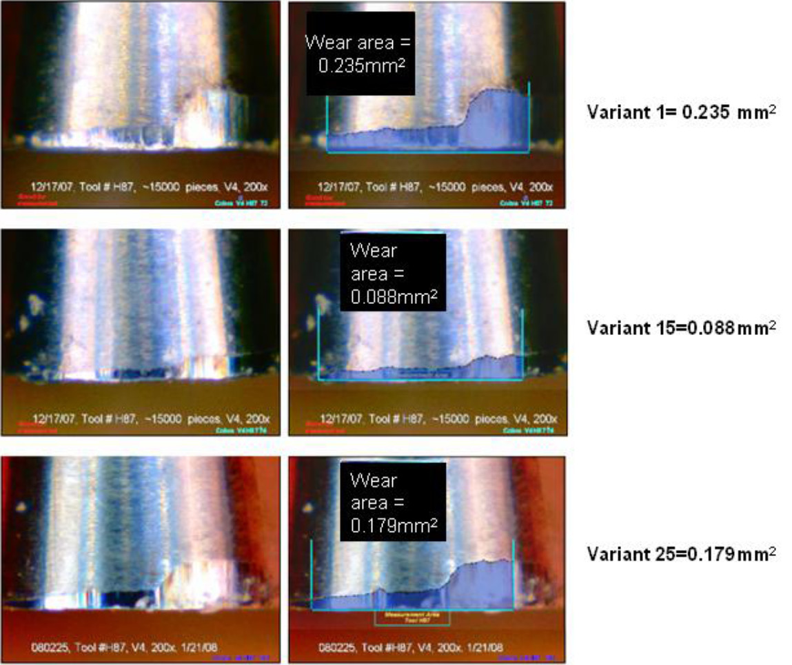
In this following evaluation, the second set of conditions (V115) resulted in the lowest level of wear of the three setups. This trial used only three tools. Each tool produced 15,000 parts.
The second set of conditions represents approximately a 100% increase in tool life. If a reduced cycle time is desired, an increased cutting speed is a viable option knowing that this lubricant or lubricant condition delivered a substantial decrease in tool wear.
Both V1 and V25 conditions resulted in excessive wear. From these results, it is obvious that the V15 conditions are conducive to better tool wear.
This measurement technique has been applied to evaluations of tools, tool coatings, coolants and MQL. This measurement technique had an error of about 0.003 mm2.