MEMS: An end to fear of contact
Linda Day, Contributing Editor | TLT Cover Story February 2010
New lubrication technologies open the door to micromotors, turbines, gears, sliding mechanisms and other innovative contact applications.
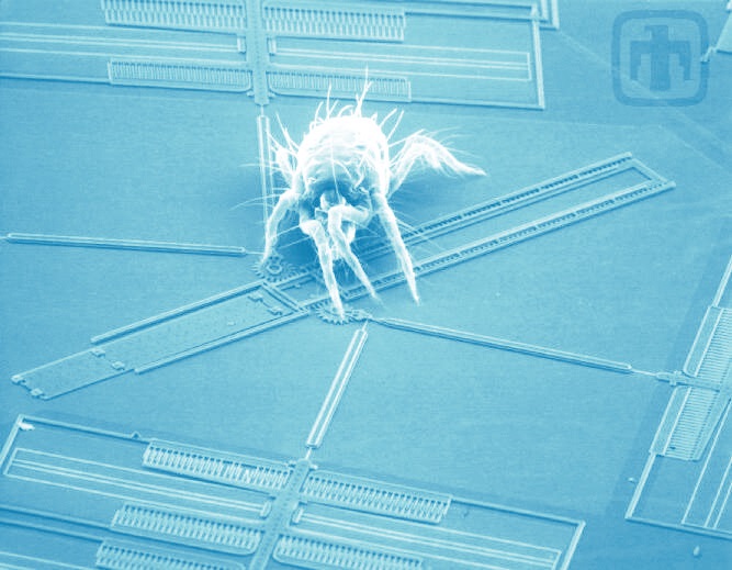
A spider mite dwarfs this MEMS drive device.
www.canstockphoto.com
KEY CONCEPTS
•
Micro-electrical-mechanical systems have made giant strides and are now poised to tackle exciting new applications.
•
Adhesion problems have been solved by self-assembled monolayers.
•
Vapor-phase and new hard-coating lubrication schemes enable MEMS with moving parts to operate nearly indefinitely without significant wear.
Systems designers need to realize that they don’t have to fear MEMS with contacting surfaces anymore,” says STLE-member Dr. Mike Dugger, member of the technical staff at Sandia National Laboratories in Albuquerque, N.M. “The new approaches to MEMS lubrication can keep these devices working nearly indefinitely.”
Dr. Jacqueline Krim, currently a visiting professor at Duke University in Durham, N.C., on sabbatical leave from North Carolina State University where she is a professor of physics, concurs. “I think progress on MEMS applications has been delayed 30-35 years because of lubrication problems,” she says. “But given where we are today, the potential for MEMS commercial applications should skyrocket.”
MEM—ORY LANE
Perhaps Richard Feynman is the true father of MEMS—micro-electrical-mechanical systems. His now famous lecture, “There’s Plenty of Room at the Bottom,” was a prophetic 1959 vision that didn’t begin to be recognized until semiconductor fabrication technologies emerged in the late ’60s. The ’70s saw development of microscopic silicon pressure sensors and accelerometers, and by the mid-’80s microscope images of tiny mechanical gizmos dwarfed by a spider mite were generating worldwide oohs and ahhs. Alas, MEMS gears and hinges could be demonstrated in the lab, but most of them worked only for a minute or two before grinding to a halt.
So for the past 30 years, MEMS have mostly proven useful for applications with no contact or sliding. High-end applications include pressure sensing (in-vivo catheters), bio-MEMS (chemical and biochemical analysis and point-of-use diagnostics), RF communication, IR imaging and microphones. MEMS also appear widely in consumer products: inkjet printers, the accelerometers that deploy your car’s airbags, and the tiny gyroscopes that sense the movement of your Nintendo Wii or the way you rotate your iPhone.
The exception to the no-contact rule was Texas Instruments’ digital micromirror display (DMD) technology. Widely used in computer projectors, DMDs feature millions of aluminum MEMS mirrors that tilt toward one landing pad to reflect light and then snap back to another landing pad when the pixel is off.
But what about MEMS gears, motors, turbines and sliders, where there’s contact and friction? How do you solve adhesion, friction and wear problems?
 MEMS appear widely in consumer products like the accelerometers that deploy your car’s airbags.
www.canstockphoto.com
STICTION, SAMS AND HARD COATINGS
Adhesion at the nanoscale is a consequence of van der Waals forces, electrostatic interactions between surface dipoles and charges, as well as capillary phenomena and chemical forces. In small mechanical structures, the main source of adhesion is capillary forces. It was first observed in the magnetic recording industry, where water condensed between the recording head and the hard disk surface. The phenomenon was dubbed “stiction,” a term that stuck and has become a catch-all for MEMS structures that stick together, regardless of the physical origin of the force. Adhesion and applied contact force combine to create a major obstacle for MEMS devices to overcome.
“MEMS are made by etching away components,” Krim explains, “and the last thing you do is rinse them to get rid of the etching material. When they come out of the final rinse water, they tend to be all stuck together due to capillary effects. It’s like having a greasy hair day.”
Various drying schemes could solve the hair-day problem (e.g., the University of California-Berkeley’s supercritical CO
2), but that wasn’t enough. “Even after drying, the surfaces would stick when they came into contact again,” says Roya Maboudian, professor of chemical engineering at the University of California-Berkeley and associate director of the Center of Integrated Nanomechanical Systems (COINS). “The surface-to-volume ratio is so high—and so is the surface energy of silicon, which is the dominant material in this technology.”
Maboudian was the first to recognize the need for chemical modifications to the surface. Currently on sabbatical, she is in Germany at the Leibniz Institute for New Materials in Saarbruecken, where TLT talked with her.
“The core expertise in our group is on surface and interfacial science and engineering, as well as micro- and nanosystem technology,” she says. “In the M/NEMS area, we’ve been looking at stiction, friction, wear, corrosion, anything that can affect long-term reliability. We’ve developed microinstruments to quantify and decipher tribological phenomena and materials and schemes to suppress them.” One of her group’s instruments actually monitors the evolution of MEMS contacting surfaces
in-situ. “Before this, characterizations of contact were all postmortem,” she says. “You’d have to tear apart the device after running it to see what was going on. With this instrument, we can follow the surface evolution of contact in real-time.”
Those in MEMS research are unanimous in praise for Maboudian’s key contribution to the field: organic self-assembling monolayers or SAMs. These are thin films, usually only a single molecule thick, that self-assemble on a MEMS device and reduce or eliminate stiction. “Commercially, most of these devices don’t involve repetitive high-pressure contact,” Maboudian says, “and organic SAMs offer an effective solution.”
Since her early proof-of-concept results, SAMs have been scaled up for manufacturing and are now used almost universally. The inherent advantage of SAMs is that they do not affect the packaging and encapsulation steps, which are often the most-expensive and device-specific part of the MEMS manufacturing process. SAMs also are effective in hindering electrochemically induced corrosion in MEMS.
For situations where repetitive contact and wear are issues, Maboudian’s group is exploring self-healing monolayers, surface coatings that can be replenished from an overpressure in the package. “Texas Instruments uses this approach for their DMDs, which can last for hundreds of billions of impact cycles,” Maboudian notes. “We have also demonstrated that hard coatings such as silicon carbide (SiC) or titania (TiO
2) are quite effective. Silicon carbide is remarkable because it exhibits self-lubrication—the more we run them the better they get! It’s the first time we’ve seen anything like it. We’re also leveraging advances in deposition technology that allow hard coatings like Al
2O
3 and TiO
2 to be deposited at low temperatures.”
While Maboudian looks to SAMs, self-healing monolayers and hard coatings to solve friction and wear, Dugger, Krim and Seong Kim are moving in another direction.
ANSWER IN THE VAPOR
“In 2002, I went to the STLE conference in Houston,” says Seong Kim, professor of chemical engineering at Penn State University in University Park, Pa. “Everyone was talking about MEMS lubrication. People tried to put coatings on MEMS surfaces: diamond-like carbons or organic self-assembled monolayers (SAMs) or harder coatings like titanium carbide, titanium nitride, silicon nitride or even aluminum oxide. Those coatings provide some improvement in lifetime, but none of them last long enough. A coating is like one layer of bubble packing wrap: If you pop the bubble, you lose the effect.”
How severe is the wear problem? “Say you have a huge machine with 1 cm of lubricant coating that will last for 10 years,” Kim says. “If you assume the same wear rate at the 1 nm scale, the coating would last only 30 seconds. The macroscale has a much larger margin of safety.”
Kim agrees that a hard coating lasts longer than an organic SAM, but still, once it is removed, bare silicon oxide is exposed. He also points to problems depositing hard coatings and potential issues with thermal coefficients of expansion—a coated MEMS device may warp when the temperature changes, something like the thermocouple in an old-time thermostat.
Krim also has taken a hard look at the problem. “One of the things we’ve done with our MURI project is to see if SAMs are ever going to be good lubricants,” she says. “This was a simple experiment with Mike Dugger and my student, Adam Hook. We looked at the very strongest SAMs in terms of how well they were attached to the surfaces, and they rub off very quickly.” Seong Kim continues his story: “I’m not smarter than the people trying to solve the [coating] problems,” he says, “so I do not know what coating would be better. But I had a very old Toyota Corolla at that time, it did not have any fancy coatings, and it lasted 120,000 miles. How does this car work so well? You replenish the lubricant every 3,000 miles. Voila! Continuous replenishment is the key.
“But a liquid lubricant won’t work for MEMS because the viscosity of the liquid is so high, and the force that actuates a MEMS device is very small,” Kim continues. “If you try to swim in a pool filled with honey, you cannot. You can dance in air, but you can’t dance in a swamp!”
Enter vapor-phase lubrication: Operate the MEMS device in some organic vapor, and some of the vapor will adsorb on the solid surface. But what kind of vapor? Water is no good because its high surface tension recreates the stiction problem. “I think, when there is friction between two people, we sometimes use alcohol as a lubricant,” Kim says. “And this even works for MEMS! One end of the alcohol molecule is the hydroxyl (OH) group, which has a strong interaction with the SiO2 surface. The other end is a hydrocarbon chain. All lubricants are hydrocarbon-based, so I thought this guy could have good lubrication activity.”
According to Kim, the prize for first mention of vapor-phase lubrication should go to the late Elmer Klaus of Penn State, who explored vaporized phosphates for engine lubrication back in 1976. Krim agrees that vapor-phase lubrication for macroscopic turbine engines had been in development for a very long time. “I was the first to suggest that it might work for MEMS in 1998,” she says. “Andy Gellman at Carnegie Mellon University subsequently worked out some numbers that said it could work, and I studied the same phosphate-based vapors that had been applied to the big turbines. But I couldn’t get those vapors to work well. Meanwhile, Steve Patton at the Air Force Research Laboratory showed that water vapor can lubricate MEMS in certain regimes. So it was an idea that emerged slowly.”
Using an atomic force microscope (AFM), Kim was the first to demonstrate that vapor-phase lubrication was effective for single-asperity contacts. His AFM studies showed that ethanol, propanol, butanol and pentanol all looked promising—but how to test them in MEMS devices with many more asperities? Unlike macroscale lubrication, capillary forces and water vapor play a role in MEMS, so standard pin-on-disk tests don’t suffice. The most direct method of evaluating vapor-phase lubricants for MEMS would be with a MEMS device.
MEMS TRIBOMETER DEVELOPMENT
The first MEMS device for measuring friction was developed by M.G. Lim and coworkers in 1990 at the University of California-Berkeley’s Department of Electrical Engineering and Computer Science. It measured static friction between planar surfaces of polycrystalline silicon—but most of the action in MEMS gears and actuators take place on sidewall surfaces that are generally much rougher.
Building on this idea, Dugger and post-doctoral student Donna Senft developed the sidewall tribometer in 1997. Although the device has evolved in design and complexity considerably since then, the basic premise remains the same: A clever arrangement of electrostatic actuators, or “comb drives,” applies a normal force between two sidewall surfaces while sliding one of the surfaces back and forth against the other (
see Figure 1). Comparing displacement against applied voltage provides a measurement of the interfacial forces.
 Figure 1. The MEMS tribometer invented by Dr. Mike Dugger of Sandia National Laboratories. The comb actuators on the left apply normal force to the sliding arm at the center. The actuator on the right moves that arm back and forth, about 10 microns in either direction.
In addition to measuring static friction, Dugger’s current version of the MEMS tribometer can also be used to study wear and dynamic friction while operating at realistic MEMS speeds and in any environment, from ultra-high-vacuum to vapor-phase lubricants. Dugger was using his device to study aging effects in coatings and chemisorbed monolayers before Kim’s AFM work, but the work was somewhat frustrating because his tribometers would typically seize up after only a few minutes of operation.
 Figure 2. A close-up of the MEMS tribometer’s contacting surfaces.
Doors opened when Dugger and Kim got together. They began discussing alcohol vapor lubrication of MEMS, and in 2006, David Asay, one of Kim’s students, spent a summer in Dugger’s lab. With two of Dugger’s students who were finishing up experiments on MEMS devices, Asay began by examining alcohol-vapor lubrication of silicon with a simple pin-on-disk test. Pentanol was selected for these experiments because its high flash point eliminated the possibility of exploding in the glovebox where the experiments were run. These experiments confirmed the AFM experiments: No wear could be detected on the silicon surface above a critical partial pressure of pentanol. Subsequent chemical analysis of these contact surfaces would reveal new surprises (
see The Polymer Story). Meanwhile, Asay began testing pentanol vapor on a MEMS tribometer.
Kim relays what happened next. “In a dry environment, Dugger’s MEMS tribometer would fail in one or two minutes. But when they did the same experiment in pentanol vapor, it was like the Energizer Bunny! The student left the device working and came back to Penn State. After two weeks, we got bored with waiting and stopped the device to look for wear debris. We didn’t find any! And that was the start of the vapor-phase lubrication.”
Dugger fills in the details. “Four to five years ago, with the best surface treatment technology at the time, you’d slide for a few thousand cycles, rub off the surface treatment, and the device would just get stuck. The surfaces effectively welded together, and you couldn’t exert enough force with the actuators to break them apart. Trying to find the right coating to get past this was the thrust of our research for many years. The SAMs we tested also weren’t chemically stable over long times—they could be affected by as little as 500 ppm water in the storage environment, which is far less than the military specification of 3,000 ppm for microelectronics packaging.”
Krim reproduced Kim and Dugger’s pentanol result at North Carolina State in the MURI program with a new twist—with Dugger’s help, Krim and her students ran tests in an ultra-high vacuum using quartz microbalance techniques to measure vapor uptake by surfaces. They could introduce only the vapors they wanted and measure exactly how much vapor was absorbing to the surface of the device and the effect on sliding friction.
“What we’re doing at North Carolina State is very controlled,” Krim says. “We’re comparing our data to very basic theories of sliding friction in thin films. These days we’re using ethanol instead of pentanol. If we want, we can introduce humidity and nitrogen. So far, it seems that ethanol performs better than pentanol—we have a proposal to study all this with Seong Kim.
“The point is,” Krim continues, “once you’ve got the device working, you can start the scientific studies and unravel the atomic-scale origins of why this works. It’s a whole new area opening up, and we’re really excited.”
THE POLYMER STORY
One of the puzzling features of vapor-phase lubrication with pentanol is what’s left behind after a very long period of operation. “We only stopped the device to look at the surface,” says Kim, “and we didn’t see any solid wear particles. But we saw some liquid-like deposits. With the SEM (scanning electron microscope), you cannot tell if it’s really liquid because the SEM operates in ultra-high vacuum that would evaporate any low-molecular-weight liquid.”
Further experiments by Dugger and his Sandia colleague Tony Ohlhausen using Time-of-Flight Secondary Ion Mass Spectrometry (ToF-SIMS) revealed that what appears to be a liquid was in fact a polymer with higher molecular weight than the starting vapor! Why did the polymer form? And was the good lubrication due to the pentanol vapor or the polymer?
“Our hypothesis is that polymer formation is not just a pure mechanical action of friction or shearing of molecules,” Kim says. “There’s some kind of dangling bond that is generated upon wear of the SiO
2 surface, and that could act as a catalyst for polymerization reactions.” So even if this polymer is helping with the lubrication—and this remains unclear at present, it can only be generated
in situ—you can’t make it in a laboratory and spray it on.
“The high-molecular-weight reaction product could also be the result of thermionic emission from heated asperity contacts or charge transfer,” says Dugger. “We’re still trying to determine the mechanism for formation of this material.”
 Figure 3. Initial friction coefficient measurements with the MEMS tribometer, in dry nitrogen and in nitrogen containing pentanol vapor.
A PLETHORA OF POSSIBILITIES
Figure 3. Initial friction coefficient measurements with the MEMS tribometer, in dry nitrogen and in nitrogen containing pentanol vapor.
A PLETHORA OF POSSIBILITIES
As if alcohols were not complicated enough, it turns out they are not the only effective vapor lubricants.
Dugger’s group has begun introducing other molecules with different functionalities, including pentane, pentanoic acid and 1-decene, an olefin with one double bond. All are about the same size molecule as pentanol, but the vapor pressure of pentane is about three orders of magnitude higher, and that of pentanoic acid is about an order of magnitude lower. And yet all of them lubricate at sufficient vapor pressures. The functional group doesn’t seem to make a big difference. Why?
Conjectures abound. Meanwhile, many lubricants are available, so it should be possible to choose a lubricant based on the operating temperature requirements of the MEMS device. Or, says Dugger, you might invent a cocktail that covers a wide range of temperatures, from cold start-up to hot running. He mentions that Texas Instruments uses perfluorodecanoic acid to passivate the exposed aluminum surfaces of its micromirrors. “It’s solid at room temperature,” he says, “but a projector runs at 80 C almost immediately, and the solid sublimes to a vapor. Something like that could work for MEMS in general.”
So—there are many possibilities for vapor lubricants. But how do you package a MEMS device to include them? It’s not like pouring oil into your car.
 Figure 4. A MEMS multiple gear reduction unit fabricated at Sandia National Laboratories.
PACKAGING
Figure 4. A MEMS multiple gear reduction unit fabricated at Sandia National Laboratories.
PACKAGING
“We’re still trying to figure that out,” Dugger says. One of the simplest ways of packaging a micro device in general is to glue it into a well in a ceramic package, connect the wires, and seal a lid on top to maintain the interior environment. This is where the problems arise. How do you maintain a certain concentration of lubricant in the vapor environment? First, the partial pressure of the vapor-phase lubricant must be maintained over a range that is less than the saturation pressure: If sealed in at the saturation pressure at room temperature, the vapor would condense at colder temperatures, leading to capillary effects and adhesion. Conversely, at higher temperatures, the partial pressure would decrease and ultimately fall below what’s needed to maintain effective lubrication.
Dugger notes two approaches to creating the right concentration: First, embed the lubricant in a polymer matrix that acts as both a source and a sink and paint the polymer on the inside of the device lid. “This would be a passive control concept where the lubricant’s vapor pressure is related to its saturation pressure and the degree of chemical interaction between the lubricant and the polymer matrix,” he says.
A second approach is to use a more complex molecule inside the package that can be thermally decomposed to generate the vapor desired. The compound could be painted inside the lid or grafted onto the entire surface and then decomposed to form an alcohol or olefin in a controlled but irreversible reaction.
“In principle, the material could be used up, but our calculations show that we could supply enough lubricant for 1,000 years of operation,” Dugger says. “We’ve run devices for months and months under marginal lubrication and high contact pressures to exacerbate the formation of the polymer species, and you can just start to detect some high-molecular-weight stuff in ToF-SIMS. You still don’t create enough to do a thorough chemical analysis.”
 Figure 5. This 2-axis deflecting cantilever beam developed by Roya Maboudian’s group at the University of California-Berkeley makes it possible to watch the evolution of surfaces in-situ. (Courtesy of Roya Maboudian and Applied Physics Letters)
THE FUTURE
Figure 5. This 2-axis deflecting cantilever beam developed by Roya Maboudian’s group at the University of California-Berkeley makes it possible to watch the evolution of surfaces in-situ. (Courtesy of Roya Maboudian and Applied Physics Letters)
THE FUTURE
Three years ago, TLT reported on Steve Patton’s work with MEMS switches. Today, there’s a raft of new possibilities. “It is fascinating to look back and see how far M/NEMS has come in the 16 years since we have been working on MEMS tribology,” says Maboudian. “Looking ahead, I am sure there will be many technological surprises. Given the breadth of applications for MEMS, I don’t think any one tribological solution will do it all. For example, one of my interests is sensors for high-temperature, high-pressure and corrosive environments: inside an automobile engine, or for power generation or in oil exploration and recovery. We need miniature sensors that can withstand extreme conditions, and surfaces and lubrication for those will be a whole new ball game.”
Krim says, “I think applications will take off now that we have some effective lubrication schemes. For decades, people built conventional engines first and then tried to figure out how to lubricate them. And they did the same thing with MEMS. When we go further to nanoscale dimensions, I don’t think that approach will work—I think tribology has to be built in from the outset. Even with MEMS, it’s taken us decades to lubricate them after the fact. Designers out there should have us tribologists in on their projects from the start and not just call when things go wrong!”
Dugger couldn’t agree more: “It’s time for innovation, and designers can now create just about any kind of MEMS device they want to. They just don’t have to worry about avoiding surfaces that make contact.”
Stay tuned to TLT as we’re looking forward to the next report three years from now—till then!
FOR FURTHER READING:
Kim, S.H. Asay, D.B. and Dugger, M.T., “Nanotribology and MEMS Review,”
NanoToday,
2 (5), October 2007.
Maboudian, R. and Howe, R.T. (1997), “Critical Review: Adhesion in Surface Micromechanical Structures,”
Journal of Vacuum Science & Technology B,
15, pp. 1-20.
Maboudian, R. and Carraro, C. (2004), “Surface Chemistry and Tribology of MEMS,”
Annual Review of Physical Chemistry,
55, pp. 35-54.
Liu, F., Laboriante, I., Bush, B., Roper, C.R., Carraro, C. and Maboudian, R. (2009), “In-Situ Studies of Interfacial Contact Evolution via a 2-axis Deflecting Cantilever Microinstrument,”
Applied Physics Letters,
95, 131902.
Ashurst, W.R., Wijesundara, M.B.J., Carraro, C. and Maboudian, R. (2004), “Tribological Impact of SiC Encapsulation of Released Polycrystalline Silicon Microstructures,”
Tribology Letters,
17 (2), pp. 195-198.
Asay, D.B., Dugger, M.T. and Kim, S.H. (2008), “In-Situ Vapor-Phase Lubrication of MEMS,”
Tribology Letters,
29 (1), pp. 67–74.
Asay, D.B., Dugger, M.T., Ohlhausen, J.A. and Kim, S.H. (2008), “Macro- to Nanoscale Wear Prevention via Molecular Adsorption,”
Langmuir,
24, pp. 155-159.
Krim, J. and Abdelmaksoud, M. (1998), “Nanotribology of Vapor-Phase Lubricants,” in
Tribology Issues and Opportunities in MEMS, B. Bhushan, ed. (Kluwer Academic, Dordrecht), pp. 273-284.
Abdelmaksoud M., Bender J.W. and Krim J. (2002), “Nanotribology of a Vapor-Phase Lubricant: A Quartz Crystal Microbalance Study of Tricresylphosphate (TCP) Uptake on Iron and Chromium,”
Tribology Letters,
13 (3), pp. 179-186.
Hook, D.A., Timpe, S.J., Dugger, M.T. and Krim, J. (2008), “Tribological Degradation of Fluorocarbon Coated Silicon Microdevice Surfaces in Normal and Sliding contact,”
Journal of Applied Physics,
104 (3), Article 034303.
 Linda Day is a free-lance writer based in Houston. You can reach her at linda@daycreative.com
.